Inverter control methodology for distributed generation sources connected to a utility grid

Inactive Publication Date: 2005-11-17
ADVANCED ENERGY CONVERSION
View PDF11 Cites 90 Cited by
  • Summary
  • Abstract
  • Description
  • Claims
  • Application Information

AI Technical Summary

Benefits of technology

[0021] The disclosed invention provides better stability of its MPPT by virtue of its output-current control. The feed-forward and gain normalization help to keep the output current distortion low. Without it, the distortion can lead to unexpected changes in output power when the current gain is incremented or decremented by the MPPT. Thus, this can lead to instability. Also, the output current is normalized with respect to the utility RMS voltage to allow for consistent changes in output power regardless of the grid RMS voltage; hence, the MPPT is stable over any range of the utility RMS voltage. The added features of the output-current control help to prevent instability of the MPPT.
[0022] Since the output current waveform has less distortion, the net output power is closer to its expected value for a given value of the current gain. This eliminates the need to measure the output power so the controller can account for instabilities or hanging that might occur—a case similar to the hanging and instability that can arise when there is no account for the inverter efficiency as described above, except in this case it is correlated with power at the output (power into the utility). In either case, instability and hanging can arise for those systems that sense the array power for control, whereby the output power is not consistent with the commanded current gain, or the eff

Problems solved by technology

Some algorithms can get lost in determining on which side of the MPP the array is operating, or in making changes that are too large, causing the algorithm to bounce back a

Method used


Image

  • Inverter control methodology for distributed generation sources connected to a utility grid
  • Inverter control methodology for distributed generation sources connected to a utility grid
  • Inverter control methodology for distributed generation sources connected to a utility grid

Examples


Embodiment Construction

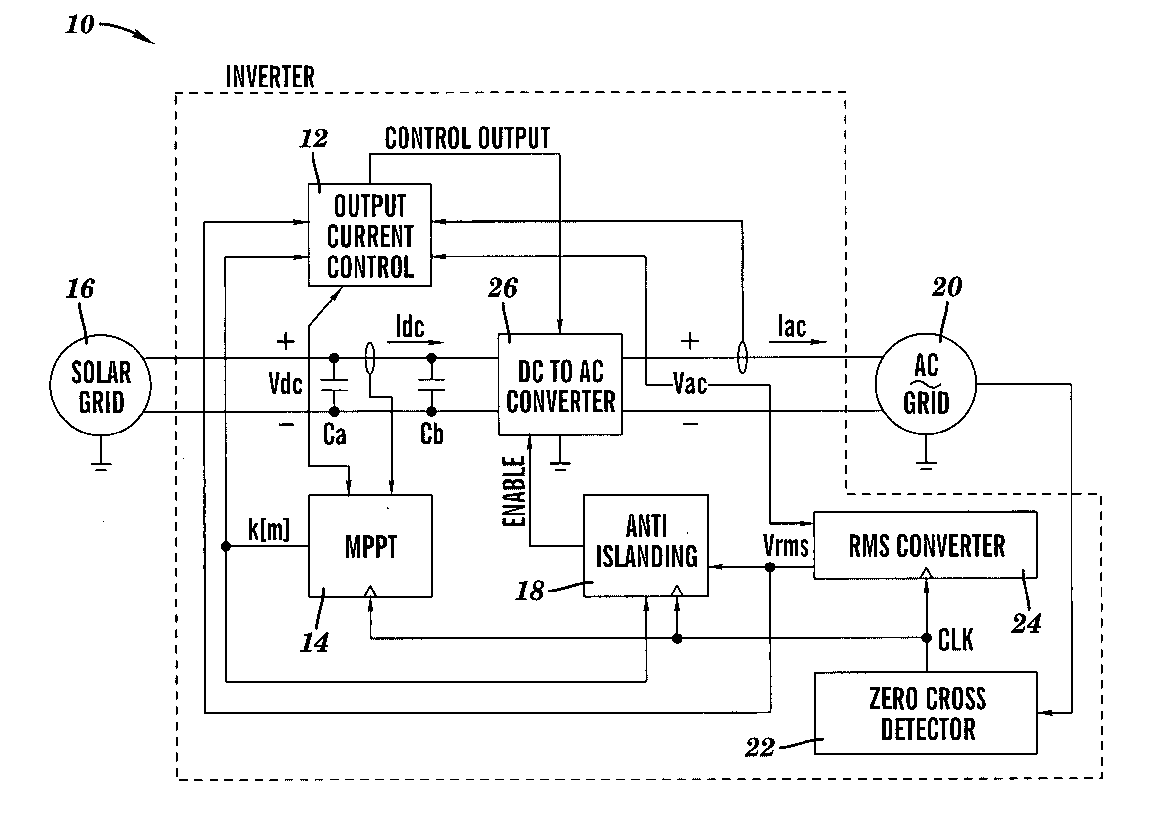
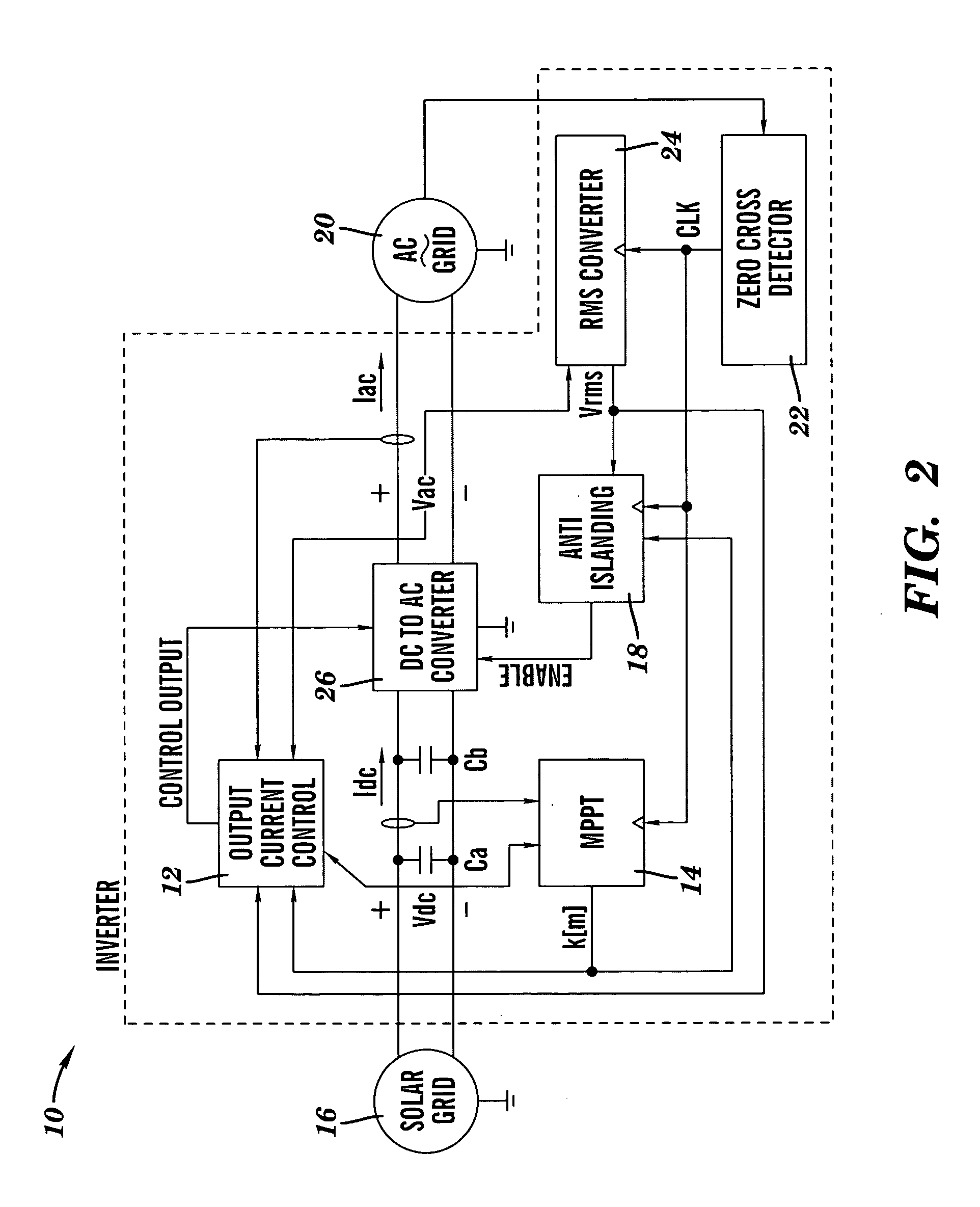
[0041] A control system for an inverter 10 in accordance with the present invention is illustrated in FIG. 2. As shown, the inverter control system has three main components: an output current control 12, a maximum power point tracking (MPPT) system 14 for determining the peak power operating point of a solar grid 16, and an anti-islanding controller 18. These control elements contain both individual enhancements and collective enhancements over the prior art.

[0042] In FIG. 2, the solar grid 16 (also known as a solar PV array) comprises a combination of solar-photovoltaic cells from which the inverter 10 draws power. The AC-grid 20 represents the utility into which power is sourced by the inverter 10. A zero cross detector 22 provides a clock signal CLK used to synchronize execution of an RMS voltage calculation by an RMS converter 24, anti-islanding detection by the anti-islanding controller 18, and execution of an MPPT algorithm by the MPPT system 14. A direct current (DC) to alt...


PUM


Abstract

The present invention provides an improved control methodology for maximum power point tracking (MPPT), anti-islanding, and output current regulation for distributed generation sources connected to a utility grid. The control includes enhancements for MPPT and regulating the inverter output-current that is sourced into the utility grid. In addition, the functions associated with MPPT, anti-islanding detection and output current regulation are integrated together; the MPPT algorithm operates in conjunction with the anti-islanding detection, and the output current regulation operates in conjunction with the MPPT algorithm.

Description

BACKGROUND OF THE INVENTION [0001] 1. Technical Field [0002] The present invention relates generally to distributed generation systems. More specifically, the present invention provides an inverter control methodology for maximum power point tracking (MPPT), anti-islanding, and output current regulation for distributed generation sources connected to a utility grid. [0003] 2. Related Art [0004] The available power output from a solar photovoltaic (PV) array (comprised of one or more solar photovoltaic panels configured in some combination of parallel and series) depends on the amount of sunlight hitting the array (the insolation) and the array temperature. The output power is the product of the array voltage and array current. It is a characteristic of solar PV arrays, as well as other distributed energy sources, that the output voltage drops as the output current increases. With solar PV arrays, the output voltage drops monotonically with increasing output current. At some level of...

Claims


Application Information

Patent Timeline
IPC IPC(8): H02H3/00H02J3/38
CPCH02J2003/388H02J3/383Y02E10/763Y02E10/563H02J3/386H02J3/388H02J2300/28H02J2300/24H02J3/381Y02E10/56Y02E10/76
Inventor BASHAW, TRAVIS B.CARPENTER, ROBERT T.TORREY, DAVID A.
Owner ADVANCED ENERGY CONVERSION
Why Eureka
Try Eureka