Perpendicular magnetic recording medium, method of producing the same, and magnetic storage device

a magnetic storage technology, applied in the field of a method of producing the same, and a magnetic storage device, can solve the problems of increasing noise generated in the medium, limited heating temperature, and spread so as to reduce the noise in the perpendicular magnetic recording medium, reduce and improve the distribution of the diameter of the magnetic particles.

Active Publication Date: 2005-11-17
RESONAC CORP
View PDF6 Cites 44 Cited by
  • Summary
  • Abstract
  • Description
  • Claims
  • Application Information

AI Technical Summary

Benefits of technology

[0042] According to the present invention, by setting a deposition speed of forming the underlayer to be in a predetermined range, and setting a pressure in an atmosphere gas to be in a predetermined range, it is possible to form the underlayer in which the granular crystals are separated by the interstices. As a result, the distribution of diameters of the magnetic particles is improved, magnetic interaction between the magnetic particles is reduced or made uniform, and noise in the perpendicular magnetic recording medium is reduced. This makes it possible to increase the recording density.

Problems solved by technology

Further, in order to avoid crystallization of the soft magnetic underlayer, the heating temperature is limited when forming the recording layer.
However, if merely forming the Ru layer under the recording layer, crystals of the magnetic particles grow on the surface of the granular crystals of the Ru film, and depending on the sizes and arrangement of the granular crystals, the magnetic particles may combine with each other; as a result, sufficient isolation between the magnetic particles cannot be achieved, the distribution of diameters of the magnetic particles becomes more spread, and consequently, noise generated in the medium increases.
As a result, the distance between the soft magnetic underlayer and the recording layer is large, and this increases the magnetic field of the magnetic head required for recording.
Further, because the distribution of the magnetic field of the magnetic head becomes more spread, data on neighboring tracks may be erased accidentally.

Method used


Image

  • Perpendicular magnetic recording medium, method of producing the same, and magnetic storage device
  • Perpendicular magnetic recording medium, method of producing the same, and magnetic storage device
  • Perpendicular magnetic recording medium, method of producing the same, and magnetic storage device

Examples


first embodiment

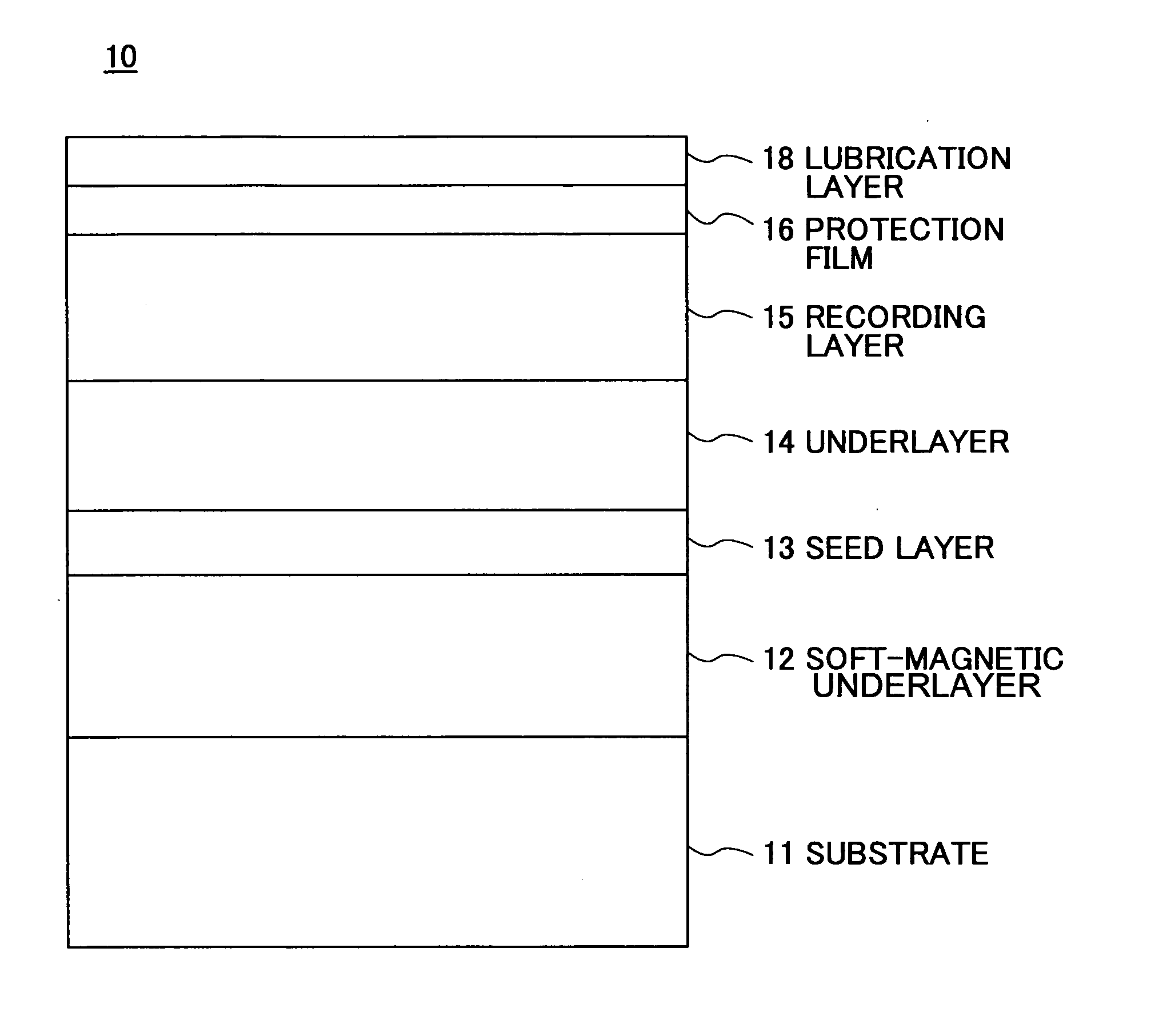
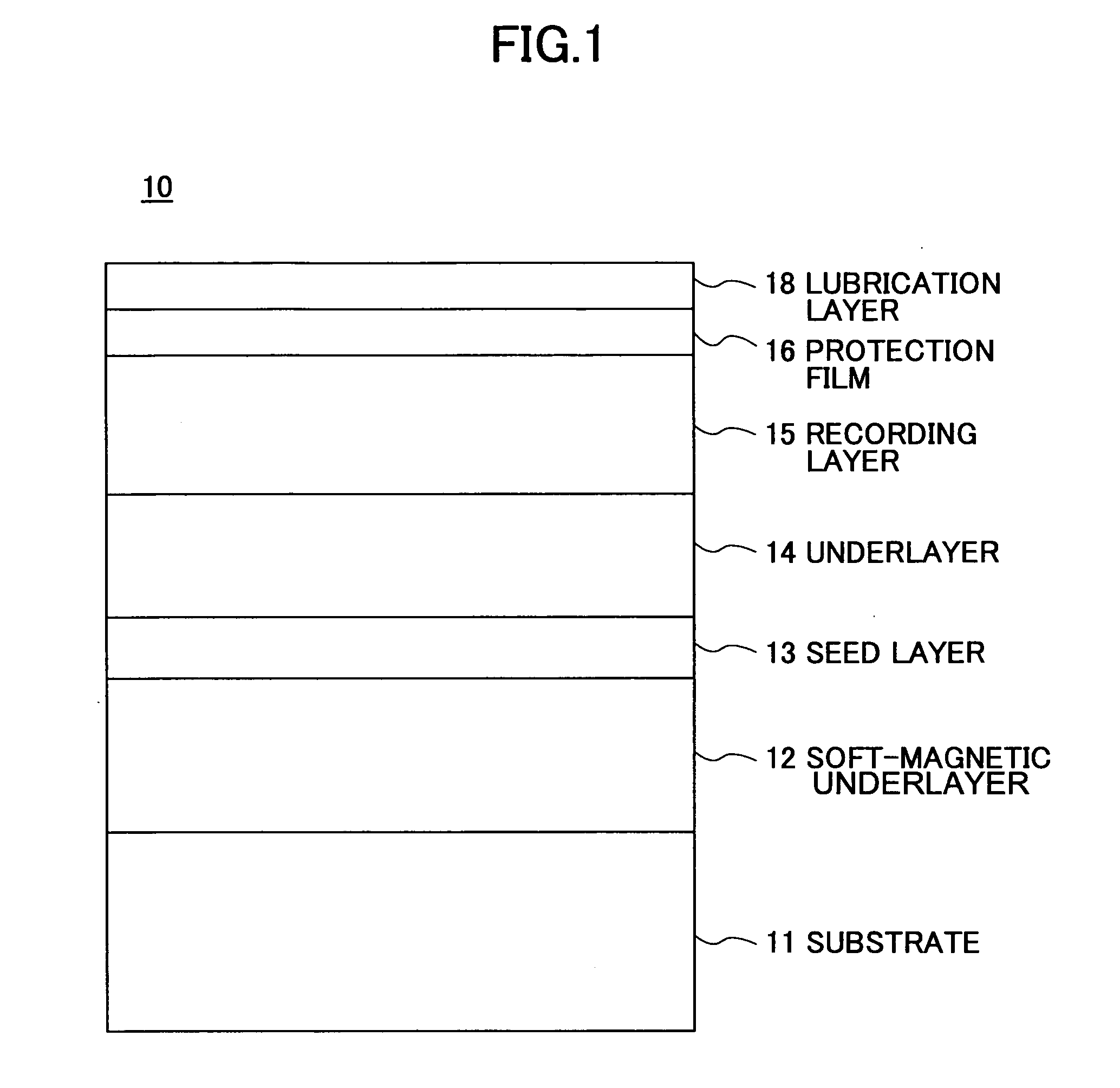
[0061]FIG. 1 is a schematic cross-sectional view of a perpendicular magnetic recording medium according to a first embodiment of the present invention.

[0062] As illustrated in FIG. 1, the perpendicular magnetic recording medium 10 includes a substrate 11, and a soft-magnetic underlayer 12, a seed layer 13, an underlayer 14, a recording layer 15, a protection film 16, and a lubrication layer 18 stacked on the substrate 11 in order.

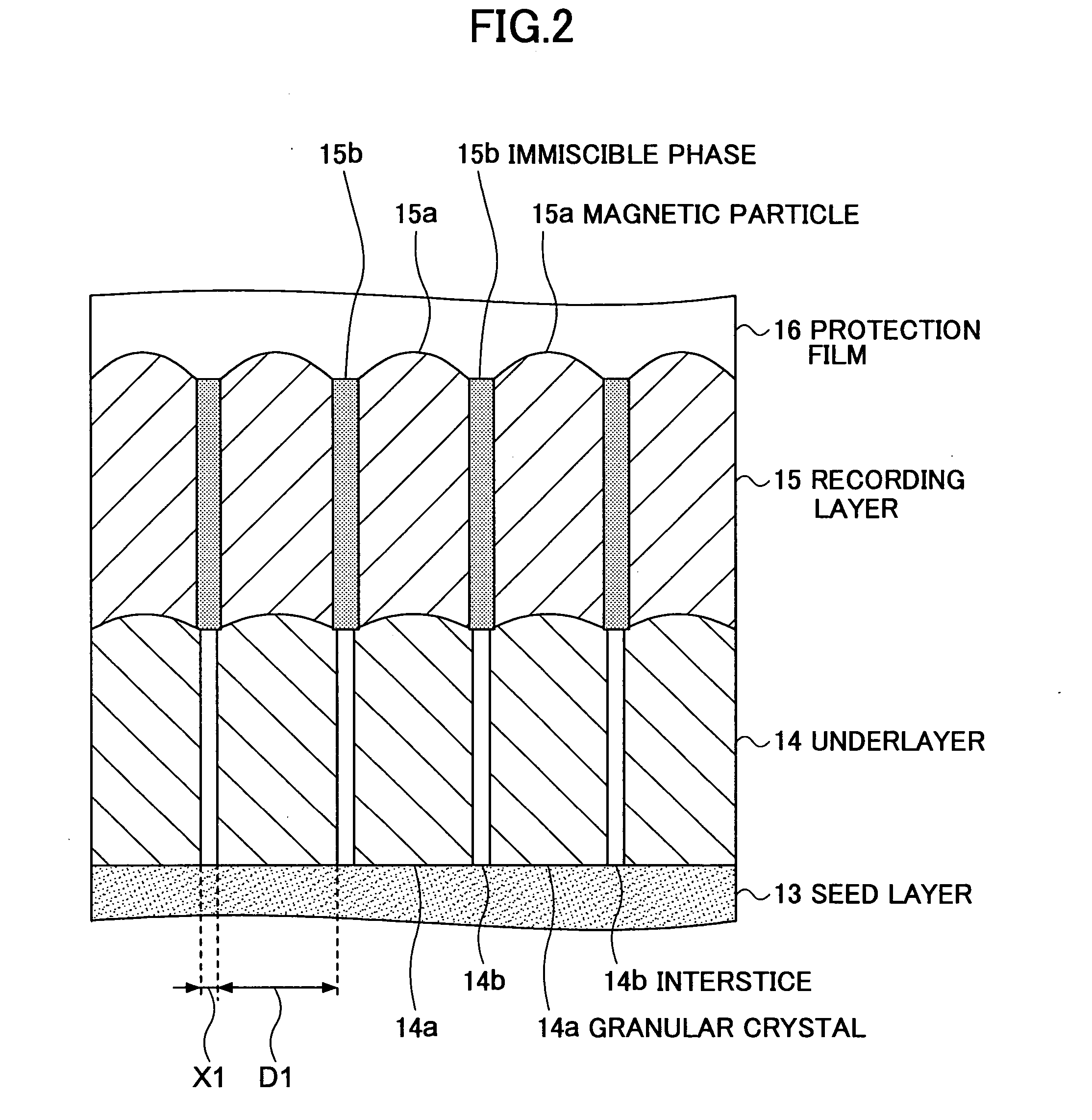
[0063] In the underlayer 14, as will be described below with reference to FIG. 2, granular crystals are formed to be separated from each other.

[0064] In the perpendicular magnetic recording medium 10, because magnetic particles in the recording layer 15 grow on the granular crystals in the underlayer 14, the isolation condition of the magnetic particles is improved, and as a result, noise in the perpendicular magnetic recording medium 10 is reduced, and the perpendicular magnetic recording medium 10 is capable of recording at a high density.

[0065] The s...

second embodiment

[0123] In the perpendicular magnetic recording medium of the second embodiment, another underlayer is further provided between the seed layer and the underlayer.

[0124]FIG. 3 is a schematic cross-sectional view of a perpendicular magnetic recording medium 20 according to the second embodiment of the present invention.

[0125]FIG. 4 is an enlarged schematic view of a portion of the perpendicular magnetic recording medium 20 according to the second embodiment of the present invention.

[0126] In FIG. 3 and FIG. 4, the same reference numbers are used for the same elements as those in the previous embodiment, and overlapping descriptions are omitted. Further, in FIG. 3 and FIG. 4, the underlayer 14 the same as that shown in FIG. 1 and FIG. 2 is referred to as “the first underlayer 14”, and the newly provided underlayer is referred to as “the second underlayer 21”.

[0127] As illustrated in FIG. 3 and FIG. 4, the perpendicular magnetic recording medium 20 includes a substrate 11, and a soft...

example 1

[0150] This example shows a perpendicular magnetic recording medium having the same configuration as the perpendicular magnetic recording medium 10 of the first embodiment.

[0151] The perpendicular magnetic recording medium of this example includes, in order from the substrate side, a Si substrate, an amorphous silicon oxide film, a soft-magnetic underlayer, a seed layer, an underlayer, a 16 nm recording layer, and a protection film.

[0152] The soft-magnetic underlayer was formed from a CoZrNb film and was 20 nm in thickness. The seed layer was formed from a Ta film and was 3 nm in thickness. The underlayer was formed from a Ru film and was 13.2 nm in thickness. When forming the recording layer by sputtering, the sputtering target included 88.5% Co67Cr7Pt26 in volume and 11.5% SiO2 in volume. The protection film was formed from a carbon film and was 3 nm in thickness.

[0153] The CoZrNb film, the Ta film, and the carbon film were formed by using a DC magnetron in an atmosphere of Ar ...


PUM

PropertyMeasurementUnit
diameteraaaaaaaaaa
thicknessaaaaaaaaaa
thicknessaaaaaaaaaa

Abstract

A perpendicular magnetic recording medium is disclosed that includes a recording layer having a columnar granular structure possessing an appropriate diameter distribution and uniform arrangement of magnetic particles. The perpendicular magnetic recording medium includes a substrate, and a soft-magnetic underlayer, a seed layer, an underlayer, a recording layer, a protection film, and a lubrication layer stacked on the substrate in order. The underlayer includes granular crystals formed from Ru or a Ru alloy and interstices separating the granular crystals from each other so as to isolate individual granular crystals. A continuing film formed from Ru or Ru alloys may be provided below the underlayer.

Description

CROSS-REFERENCE TO RELATED APPLICATION [0001] The present application is a continuation-in-part application of the U.S. patent application Ser. No. 10 / 940,186 filed on Sep. 14, 2004, based on Japanese Priority Patent Applications No. 2004-144011 filed on May 13, 2004 and No. 2005-062662 filed on Mar. 7, 2005. The entire contents of these applications are hereby incorporated by reference.BACKGROUND OF THE INVENTION [0002] 1. Field of the Invention [0003] The present invention relates to a perpendicular magnetic recording medium, a method of producing the medium, and a magnetic storage device, and particularly, to a perpendicular magnetic recording medium including a magnetic layer in which magnetic particles are isolated by a non-magnetic material. [0004] 2. Description of the Related Art [0005] Recently and continuing, magnetic storage devices, for example, hard disk drives, are widely used in computers because they have low prices per bit, and store digital signals, thus enabling a...

Claims


Application Information

Patent Timeline
Patent Type & Authority Applications(United States)
IPC IPC(8): G11B5/64G11B5/738G11B5/65G11B5/667G11B5/73G11B5/84G11B5/851H01F10/16
CPCG11B5/65G11B5/667G11B5/851G11B5/7325G11B5/8404G11B5/732G11B5/7379G11B5/7369G11B5/737G11B5/708G11B5/70G11B5/68G11B5/657
Inventor MUKAI, RYOICHI
Owner RESONAC CORP
Why Eureka
Try Eureka