
Dual compressor HVAC system

Inactive Publication Date: 2005-11-24
GENERAL MOTORS COMPANY
View PDF10 Cites 105 Cited by
  • Summary
  • Abstract
  • Description
  • Claims
  • Application Information

AI Technical Summary

Benefits of technology

[0008] The electric-drive compressor allows for extended hybrid engine off operation of the vehicle while maintaining A / C comfort and enables vehicle preconditioning, wherein the electric-drive compressor runs to cool the passenger compartment prior to occupant entry. The cooling capacities of the compressors may be advantageously sized so that the operation of the HVAC system is more efficient than using a single large electric-drive or mechanical-drive compressor because each of the compressors of the present invention may be sized smaller to operate during less demand and thus consume less energy.
[0009] The HVAC system in accordance with the present invention provides greater vehicle packaging flexibility because a smaller electric-drive compressor can be located on or off the vehicle engine. In contrast, a dual-drive compressor is a larger package that must be on the engine and a single larger electric-drive compressor is more difficult to locate in the vehicle engine compartment.
[0010] The HVAC system in accordance with the present invention is well suited for use in hybrid vehicles. The HVAC system, however, may also be advantageously utilized in standard or conventional vehicles having only internal combustion engines wherein the second electric compressor runs when the cooling demand is reduced or lowered, which eliminates the parasitic load of the engine-driven compressor and increases the overall fuel efficiency of the vehicle.

Problems solved by technology

Hybrid vehicles, in particular, have had concerns because of the need to provide cooling when the engine is not running in warmer ambient conditions.
HVAC compressors are typically driven by the engine through a clutch or the like and, therefore, do not function when the vehicle engine is not running.
With the engine and compressor off, the interior of the vehicle may heat up quickly, disadvantageously requiring the engine to be operated solely for the purpose of providing cooling to the occupants of the vehicle.

Method used


Image

  • Dual compressor HVAC system
  • Dual compressor HVAC system
  • Dual compressor HVAC system

Examples


Embodiment Construction

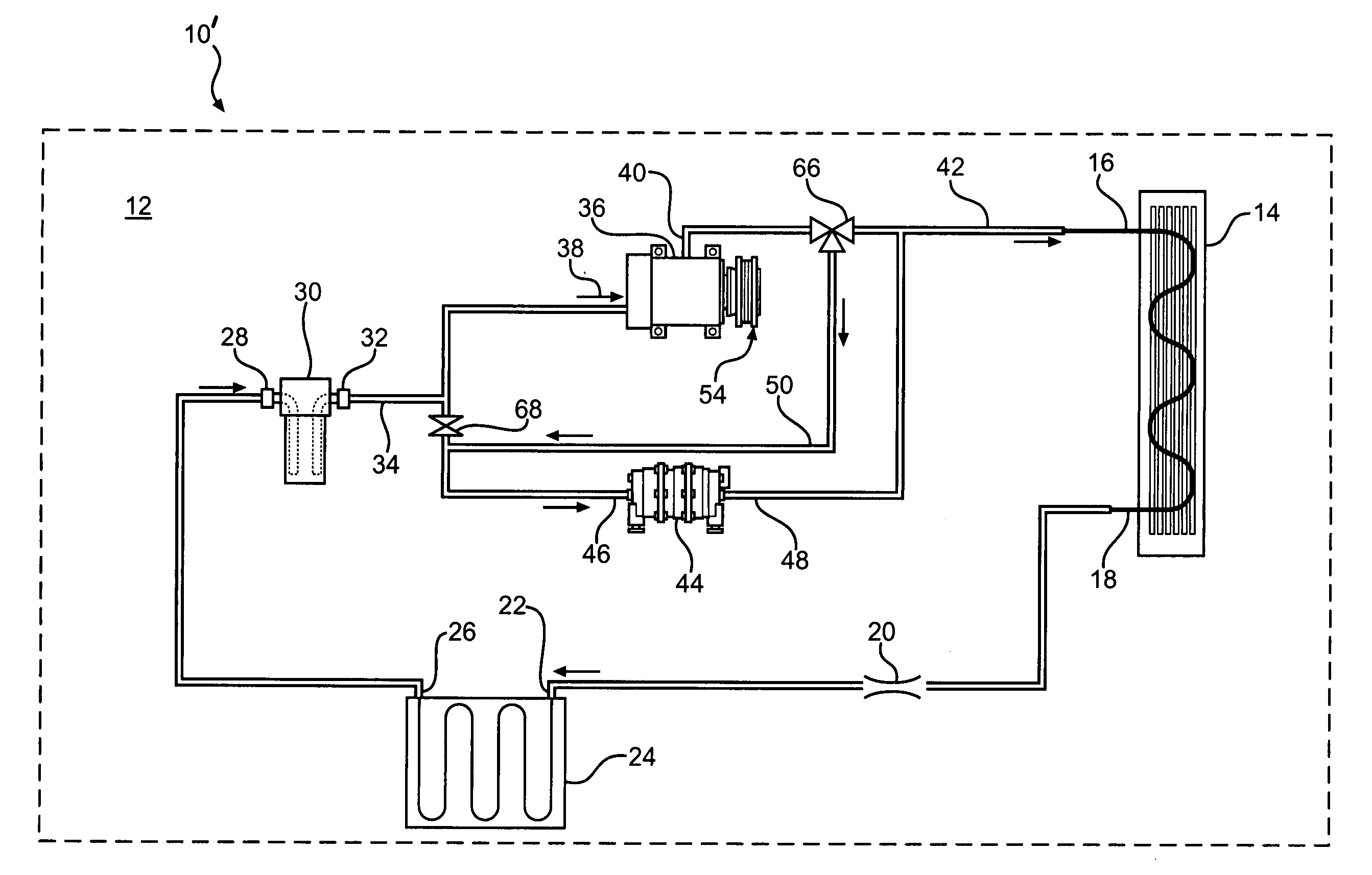
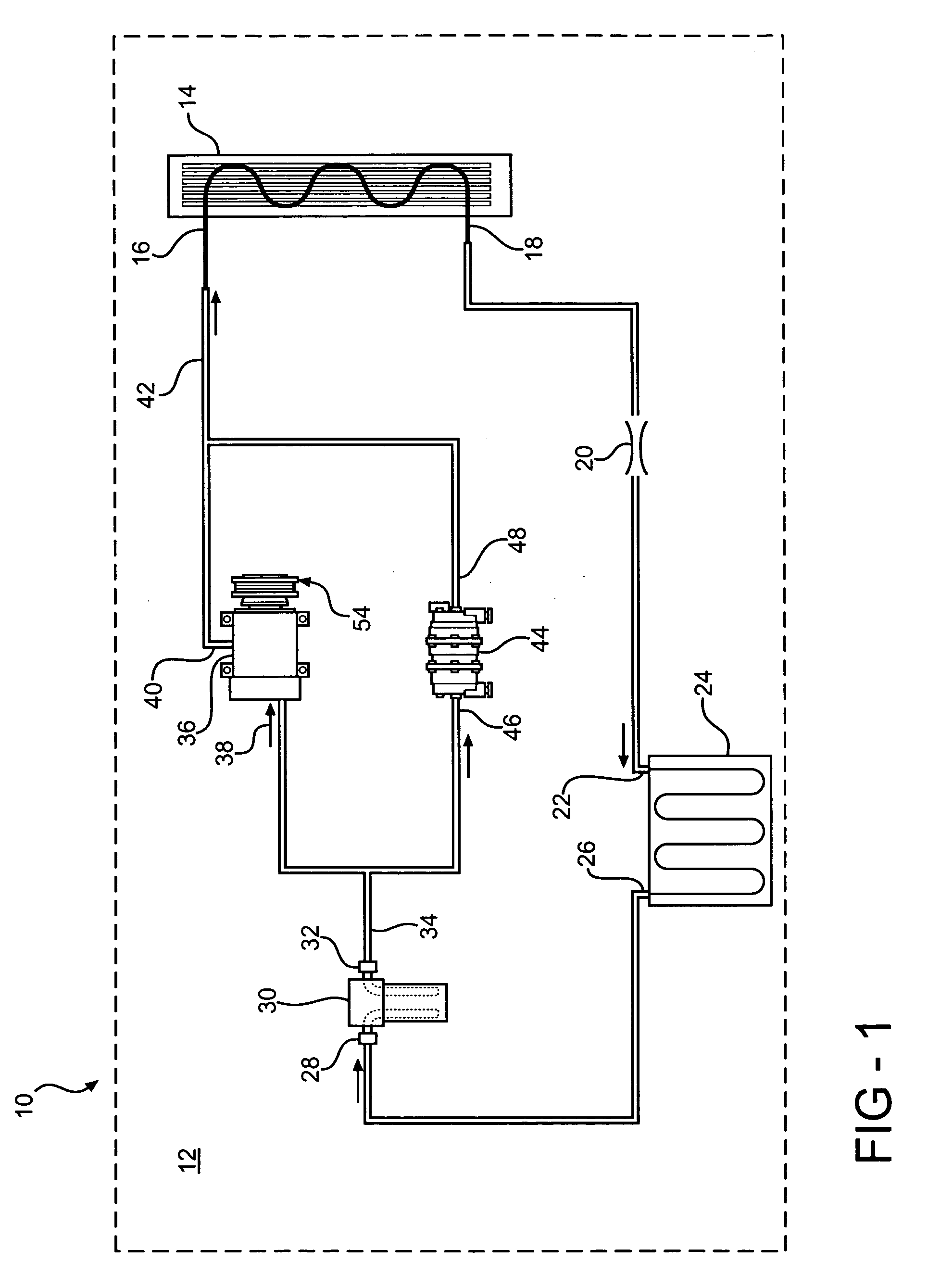
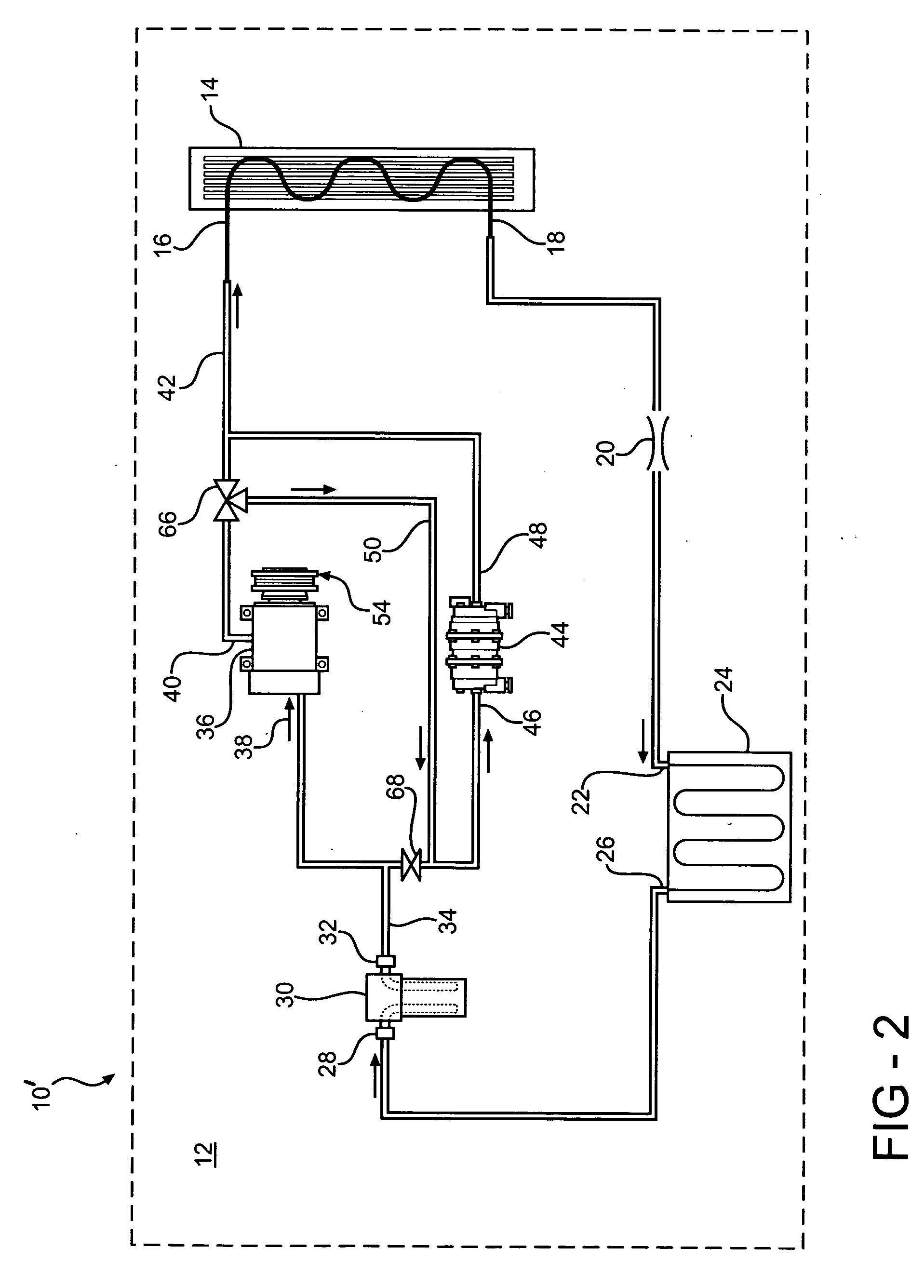
[0015] Referring now to FIG. 1, an HVAC system in accordance with the present invention is indicated generally at 10. The HVAC system 10 is disposed in a vehicle having a vehicle body, indicated schematically at 12. The HVAC system 10 includes a condenser 14 having an inlet 16 and an outlet 18. The condenser 14 includes a plurality of fins (not shown) or the like for transferring heat to ambient air or the like. The outlet 18 of the condenser 14 is in fluid communication with an orifice tube 20. Alternatively, the orifice tube 20 is replaced with a thermostatic expansion valve (not shown) or the like. The orifice tube 20 is also in fluid communication with an inlet 22 of an evaporator 24. The evaporator 22 is preferably disposed in a HVAC air duct (not shown) or the like for absorbing heat from an air stream flowing therethrough. An outlet 26 of the evaporator 24 is in fluid communication with an inlet 28 of an accumulator 30. An outlet 32 of the accumulator 30 is in fluid communica...


PUM


Abstract

The present invention concerns an automotive HVAC system for use in a vehicle having a vehicle body that includes an engine and a battery. The HVAC system has a predetermined design cooling capacity and includes a condenser and one of an orifice tube and an expansion valve in fluid communication with the condenser. A first compressor is adapted to be mechanically driven by the engine and is in fluid communication from the evaporator and in fluid communication to the condenser. A second compressor is electrically connected to and driven by the battery bank and is in fluid communication from the evaporator and in fluid communication to the condenser. Each of the compressors is selectively operable to compress refrigerant in the HVAC system during operation of the HVAC system.

Description

BACKGROUND OF THE INVENTION [0001] The present invention relates generally to automotive heating, ventilation, and air conditioning (HVAC) systems and methods of operating such HVAC systems. [0002] Hybrid vehicles, which utilize an internal combustion engine and a battery-powered electric motor for vehicle movement, are becoming more and more popular because of their increased fuel efficiency as compared to those vehicles having only an internal combustion engine. In a typical hybrid vehicle control, the engine is utilized in higher power requirement situations and the motor is utilized during starting, braking, and in lower power requirement situations. [0003] Hybrid vehicles, in particular, have had concerns because of the need to provide cooling when the engine is not running in warmer ambient conditions. HVAC compressors are typically driven by the engine through a clutch or the like and, therefore, do not function when the vehicle engine is not running. With the engine and comp...

Claims


Application Information

Patent Timeline
IPC IPC(8): B60H1/00B60H1/32F25B1/10F25B27/00F25B41/00F25B43/00F25B43/02
CPCB60H1/004B60H1/3222B60H2001/3238F25B2700/21173F25B41/00F25B2400/075F25B2700/2104F25B1/10
Inventor ZIEHR, LAWRENCE P.MAJOR, GREGORY A.NEMESH, MARK D.
Owner GENERAL MOTORS COMPANY
Learn More