Pneumatically switchable type fluid-filled engine mount

Active Publication Date: 2005-11-24
SUMITOMO RIKO CO LTD
View PDF10 Cites 42 Cited by
  • Summary
  • Abstract
  • Description
  • Claims
  • Application Information

AI Technical Summary

Benefits of technology

[0047] This advantageous form of the invention makes it possible to effectively achieve excellent vibration-damping action against a variety of vibrations that are typically a problem for most automobiles, while differing by model. Namely, the present engine mount is capable of exhibiting excellent vibration damping performance through high damping action for (1) low-frequency, large-amplitude vibration in a low-frequency range of around 10 Hz and large amplitude on the order of ±1.0 mm, such as by engine shake etc. caused by driving over a speed bump or the like, and (2) low-frequency, small-amplitude vibration in a low-frequency range of around 10 Hz and small amplitude on the order of ±0.1 mm, such as engine shake which is a problem during normal driving, while exhibiting excellent vibration damping performance through low dynamic spring constant or characteristics against (3) booming noise and other high-frequency vibration which is a problem during normal driving, falling in a high-frequency range of from 50 Hz to several hundred Hz and very small amplitude of ±0.05 mm or less. Design displacement and deformation characteristics on the part of the movable partition member in the manner described above can be advantageously achieved, for example, by tunig the characteristic frequency of the movable partition member to a frequency range of very small amplitude of ±0.05 mm or less, and utilizing the resonance action of the movable partition member; or by employing the displacement restricting member i

Problems solved by technology

However, vibration-damping action based on flow action of fluid flowing through the orifice passage is limited to a relatively narrow frequency band to which the orifice passage has been pre-tuned.
In recent years, an even higher level of vibration damping performance has come to be required, and in some instances the engine mount taught in JP-A-8-270718 is not sufficient to affords the required level of vibration damping performance.
One required characteristic is damping ability against high frequency vibration such as running booming noise, which can be a problem during driving.
Another required characteristic is damping ability against low frequency vibration such as engine shake, which can be a problem during driving.
With regard to this latter low frequency vibration, damping ability against two types of vibration, namely low frequency; large amplitude vibration which is a problem when driving over speed bumps or the like, and low frequency, small amplitude vibration which is a problem during normal driving.
However, when such a movable plate is employed, there is a risk that pressure fluctuations occurring in the pressure receiving chamber will be absorbed by displacement of the movable plate, even at times of input of small amplitude vibration in the low frequency range.
This makes it difficult to ensure adequate fluid flow level through the first orifice passage tuned to the low frequency range, resulting in the difficulty in achieving sufficient attenuating action on low frequency, small amplitude vibration.
As a result, pressure fluctuations occurring in the pressure receiving chamber during input of low frequency, small amplitude vibration or medium frequency,

Method used


Image

  • Pneumatically switchable type fluid-filled engine mount
  • Pneumatically switchable type fluid-filled engine mount
  • Pneumatically switchable type fluid-filled engine mount

Examples


Embodiment Construction

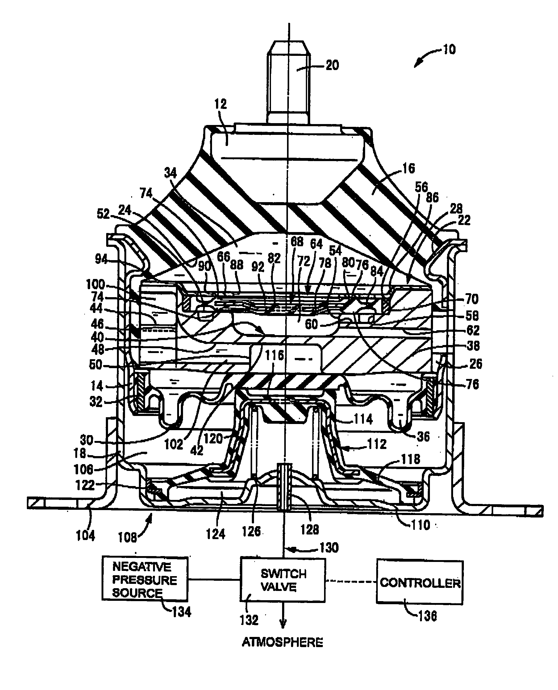
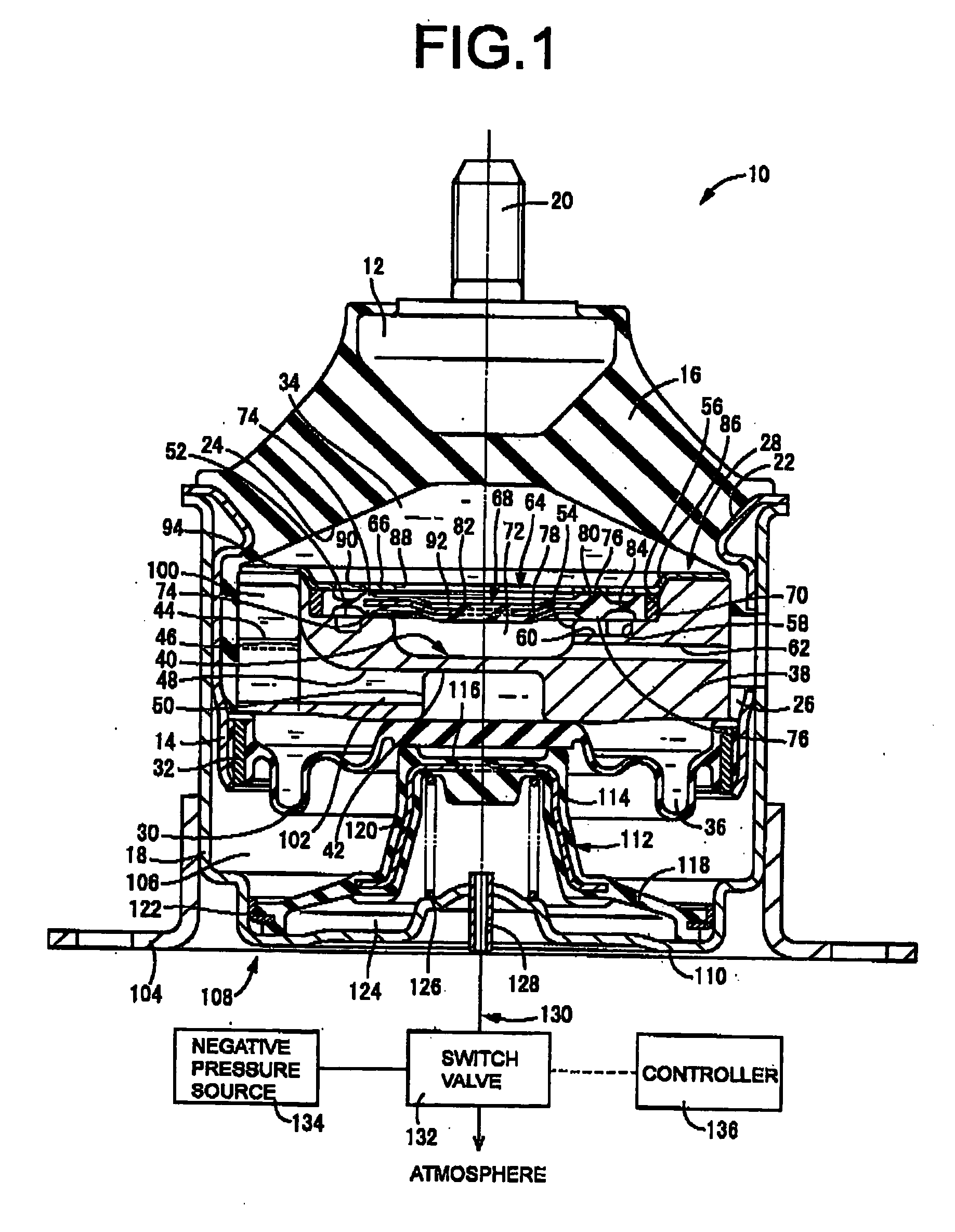
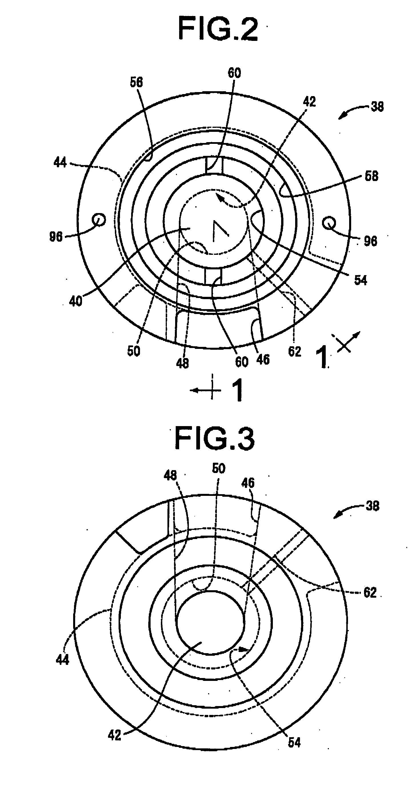
[0072] The preferred embodiments of the invention are described in detail hereinbelow with reference to the accompanying drawings, in order to provide a more specific understanding of the invention. Referring first to FIG. 1, there is illustrated an automotive vibration damping engine mount 10 as an embodiment of the invention. This engine mount 10 has a construction wherein a first mounting member in the form of a first mount fitting 12, and a second mounting member in the form of a second mount fitting 14, are elastically connected by means of a rubber elastic body 16, with the first mount fitting 12 attached to the power unit side, and the second mount fitting 14 attached to the vehicle body side, to support the power unit of the body in a vibration-damped manner. In the description hereinbelow, vertical direction shall refer to the vertical direction in FIG. 1.

[0073] To describe in more detail, the first mount fitting 12 has a block shape of generally inverted truncated cone fo...


PUM


Abstract

A fluid-filled engine mount, including: an elastic body connecting a first and a second mounting member; a pressure receiving chamber partially defined by the rubber elastic body; an equilibrium chamber partially defined by a flexible layer, a first orifice passage connecting between the pressure receiving and equilibrium chambers and tuned to a low frequency range, a second orifice passage connecting the both chambers and tuned to a medium frequency range; a valve member for opening/closing the second orifice passage and operated by a pneumatic actuator; a movable partition member including a rigid center movable plate portion and a readily deformable outer peripheral rubber film portion supported fluid-tightly by the second mount portion; and an intermediate equilibrium chamber formed opposing to the pressure receiving chamber with the movable partition member interposed therebetween.

Description

INCORPORATED BY REFERENCE [0001] The disclosure of Japanese Patent Application No. 2004-153868 filed on May 24, 2004 and No. 2004-160332 filed on May 28, 2004, each including the specification, drawings and abstract are incorporated herein by reference in its entirety, BACKGROUND OF THE INVENTION [0002] 1. Field of the Invention [0003] The present invention relates to an engine mount for vibration-isolating support of a power unit on a body of an automobile, and more particularly to a fluid-filled engine mount of improved construction, that utilizes the flow action of non-compressible fluid sealed in its interior to produce effective vibration damping action against vibration of multiple, wide frequency ranges, such as engine shake and idling vibration. [0004] 2. Description of the Related Art [0005] There are known in the art, as an engine mount for use in automotive vehicles, an engine mount of fluid-filled design having a first mount fixture and a second mount fixture for respect...

Claims


Application Information

Patent Timeline
IPC IPC(8): F16F13/26F16M1/00
CPCF16F13/262B60K5/1283F16F13/26
Inventor TANAKA, EIJI
Owner SUMITOMO RIKO CO LTD
Why Eureka
Try Eureka