Luminescent compounds with carbene ligands
a carbene ligand and carbene metal technology, applied in the direction of luminescnet screens, discharge tubes, organic chemistry, etc., can solve the problems of not being sufficiently stable for commercial devices, using carbene ligands as electroluminescent compounds, and not well known photochemistry applications of carbene ligands, etc., to achieve the effect of stable manner
- Summary
- Abstract
- Description
- Claims
- Application Information
AI Technical Summary
Benefits of technology
Problems solved by technology
Method used
Image
Examples
example 1
Synthesis of 1-phenyl-3-methylimidazolate iodide
[0125] 1-phenyl-3-methylimidazolate iodide was synthesized using the modified Ullmann coupling reaction described above. 1H NMR (250 MHz, CDCl3), ppm: 10.28 (s, 1H), 7.77-7.70 (m, 4H), 7.56-7.46 (m, 3H), 4.21 (s, 3H).
example 2
Synthesis of 1-Phenyl-3-methyl-benzimidazolate iodide
[0126] In the dark, an oven-dried 50 ml round-bottomed flask containing a stir bar was charged with CuI (0.171 g, 0.1 eq.), benzimidazole (1.273 g, 1.2 eq.), and cesium carbonate (6.138 g, 2.1 eq.) respectively. The round-bottomed flask with the contents was sealed with septa and degassed with argon for 15 minutes. Iodobenzene (1 ml, 1 eq.), 1,10-Phenanthroline (0.323 g, 0.2 eq.), and dimethylformamide (25 ml) were then successively added into the round-bottomed flask under a continuous flow of argon. The reaction mixture was degassed with argon for 30 minutes. The reaction was stirred with heating via an oil bath at 110° C. for 24 hours in the dark under nitrogen. The reaction mixture was cooled to ambient temperature and concentrated in vacuo. 10 ml of ethyl acetate was added into the concentrated reaction mixture. It was then filtered and washed with 30 ml of ethyl acetate. The filtrate was concentrated under vacuo to give the...
example 3
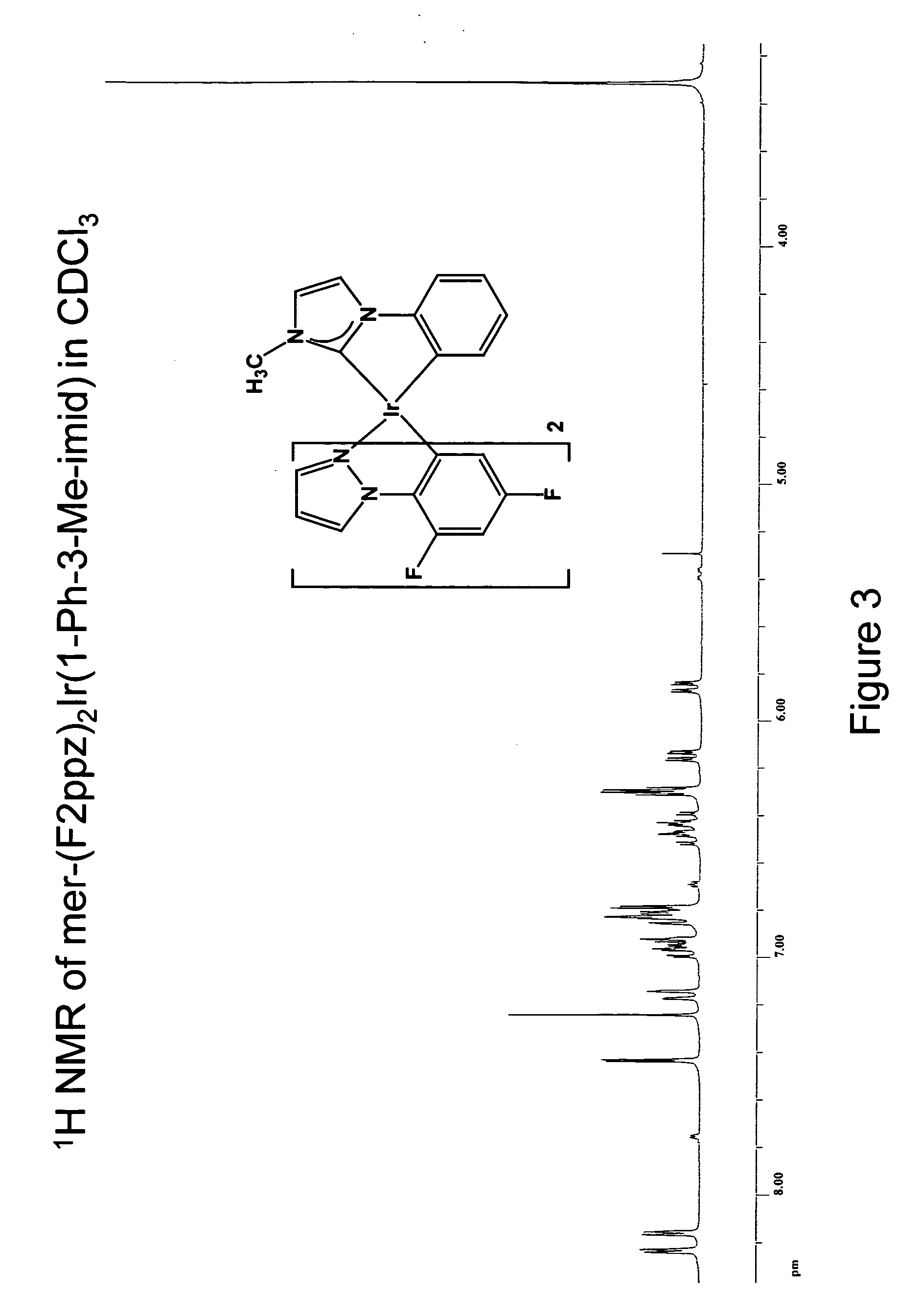
Synthesis of mer-iridium(III) bis[(2-(4′,6′-difluorophenyl)-2-pyrazolinato-N,C2′)](1-phenyl-3-methyl-imidazolin-2-ylidene-C,C2′)
[0128] A 25 ml round-bottomed flask was charged with 0.014 g of silver(I) oxide, 0.030 g of 1-phenyl-3-methyl-imidazolate iodide, 0.062 g of [(F2 ppz)2IrCl]2, and 15 ml of 1,2-dichloroethane. The reaction was stirred and heated with an oil bath at 77° C. for 15 hours in the dark under nitrogen while protected from light with aluminum foil. The reaction mixture was cooled to ambient temperature and concentrated under reduced pressure. Filtration through Celite using dichloromethane as the eluent was performed to remove the silver(I) salts. A light yellow solution was obtained and addition of methanol gave 0.025 g (30% yield) of iridium complex as a colorless solid.
[0129]1H NMR (500 MHz, CDCl3), ppm: 8.24 (d, 1H, J=2.8 Hz), 8.16 (d, 1H, J=2.8 Hz), 7.43 (d, 1H, J=1.9 Hz), 7.15 (d, 1H, J=7.5 Hz), 6.96 (ddd, 1H, J=7.5, 7.0, 1.9 Hz), 6.93 (dd, 1H, J=7.0, 1.9 Hz...
PUM
| Property | Measurement | Unit |
|---|---|---|
| temperature | aaaaa | aaaaa |
| time | aaaaa | aaaaa |
| time | aaaaa | aaaaa |
Abstract
Description
Claims
Application Information
 - R&D
- Intellectual Property
- Life Sciences
- Materials
- Tech Scout
- Unparalleled Data Quality
- Higher Quality Content
- 60% Fewer Hallucinations
Browse by: Latest US Patents, China's latest patents, Technical Efficacy Thesaurus, Application Domain, Technology Topic, Popular Technical Reports.
© 2025 PatSnap. All rights reserved.Legal|Privacy policy|Modern Slavery Act Transparency Statement|Sitemap|About US| Contact US: help@patsnap.com


