Patch sensor system for measuring vital signs

a sensor system and vital sign technology, applied in the field of vital sign patch sensor system, can solve the problems of motion-related artifacts, white coat syndrome, reducing the accuracy of measurement, etc., and achieve the effect of being easily worn

Inactive Publication Date: 2005-11-24
TRIAGE WIRELESS
View PDF95 Cites 144 Cited by
  • Summary
  • Abstract
  • Description
  • Claims
  • Application Information

AI Technical Summary

Benefits of technology

[0025] The monitor is easily worn by the patient during periods of exercise or day-to-day activities, and makes a non-invasive blood-pressure measurement in a matter of seconds. The r...

Problems solved by technology

This generates ‘noise’ in the plethysmograph, which in turn can lead to motion-related artifacts in data describing pulse oximetry and heart rate.
Ultimately this reduces the accuracy of the measurement.
Cuff-based blood-pressure measurements such as these typically only determine the systolic and diastolic blood pressures; they do no...

Method used


Image

  • Patch sensor system for measuring vital signs
  • Patch sensor system for measuring vital signs
  • Patch sensor system for measuring vital signs

Examples


Embodiment Construction

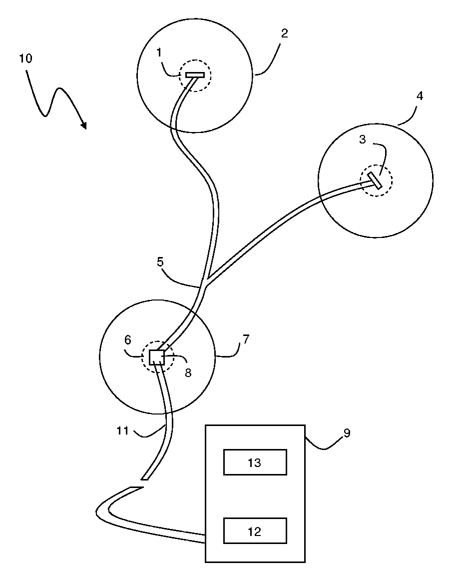
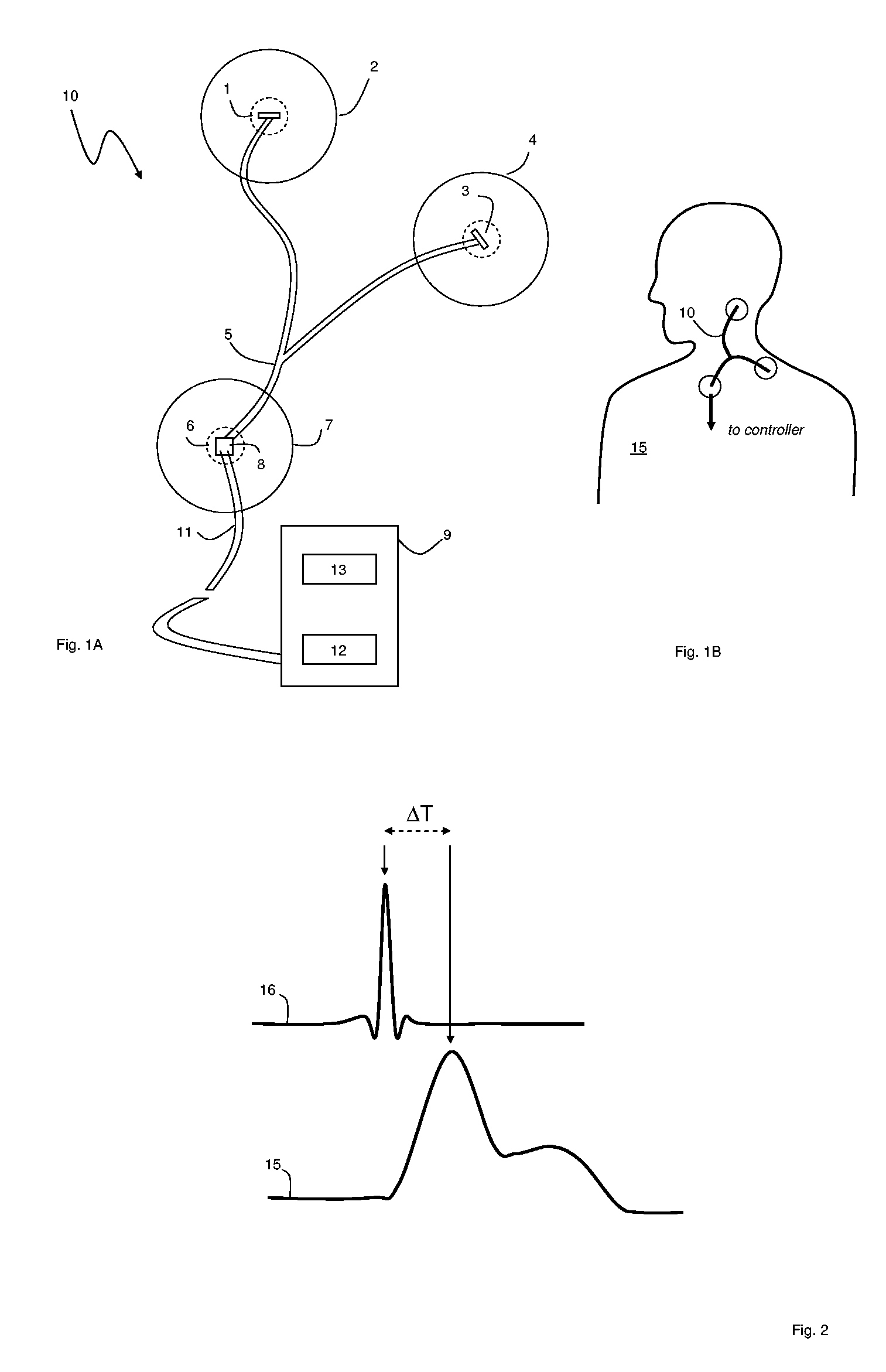
[0033]FIGS. 1A and 1B show an adhesive patch sensor system 10 according to the invention that features primary 1 and reference 3 electrodes and an optical system 6 operating in concert as described below to measure vital signs from a patient 15. The electrodes 1, 3 and optical sensor 6 each attach to the patient's skin using a separate adhesive pad 2, 4, 7, and connect to each other using a Y-shaped cable 5. During operation, the primary 1 and reference 3 electrodes detect electrical impulses, similar to those used to generate a conventional ECG, from the patient's skin. Each heartbeat generates a unique set of electrical impulses. Concurrently, the optical system 6 measures an optical waveform by detecting a time-dependent volumetric change in an underlying artery caused by blood flow following each heartbeat. The optical waveform is similar to an optical plethysmograph measured by a pulse oximeter. A circuit board 8 (described with reference to FIG. 3) attached to the optical syst...


PUM


Abstract

The invention provides a system for measuring vital signs from a patient that includes: 1) a first adhesive patch featuring a first electrode that measures a first electrical signal from the patient; 2) a second adhesive patch featuring a second electrode that measures a second electrical signal from the patient; 3) a third adhesive patch, in electrical communication with the first and second adhesive patches, featuring an optical system that measures an optical waveform from the patient; and 4) a controller that receives and processes the first and second electrical signals and the optical waveform to determine the patient's vital signs.

Description

CROSS REFERENCES TO RELATED APPLICATION [0001] This application is a continuation-in-part of U.S. patent application Ser. No. 10 / 906,315, filed Feb. 14, 2005, which is a continuation-in-part application of U.S. patent application Ser. No. 10 / 709,014, filed on Apr. 7, 2004.BACKGROUND OF THE INVENTION [0002] The present invention relates to a device, method and system for measuring vital signs, particularly blood pressure. DESCRIPTION OF RELATED ART [0003] Pulse oximeters are medical devices featuring an optical module, typically worn on a patient's finger or ear lobe, and a processing module that analyzes data generated by the optical module. The optical module typically includes first and second light sources (e.g., light-emitting diodes, or LEDs) that transmit optical radiation at, respectively, red (λ˜630-670 nm) and infrared (λ˜800-1200 nm) wavelengths. The optical module also features a photodetector that detects radiation transmitted or reflected by an underlying artery. [0004]...

Claims


Application Information

Patent Timeline
IPC IPC(8): A61B5/00A61B5/02A61B5/0205A61B5/021A61B5/0245A61B5/0408
CPCA61B5/0002A61B5/0205A61B5/02125A61B5/02438A61B5/0408A61B5/1112A61B5/6833A61B5/6814A61B2560/0412A61B2562/06A61B2560/0462A61B2562/166A61B5/14552A61B5/25A61B5/257A61B5/28A61B5/274
Inventor BANET, MATTHEW JOHNZHOU, ZHOU
Owner TRIAGE WIRELESS
Why Eureka
Try Eureka