
Light emitting device

Inactive Publication Date: 2005-12-01
HITACHI LTD
View PDF0 Cites 69 Cited by
  • Summary
  • Abstract
  • Description
  • Claims
  • Application Information

AI Technical Summary

Benefits of technology

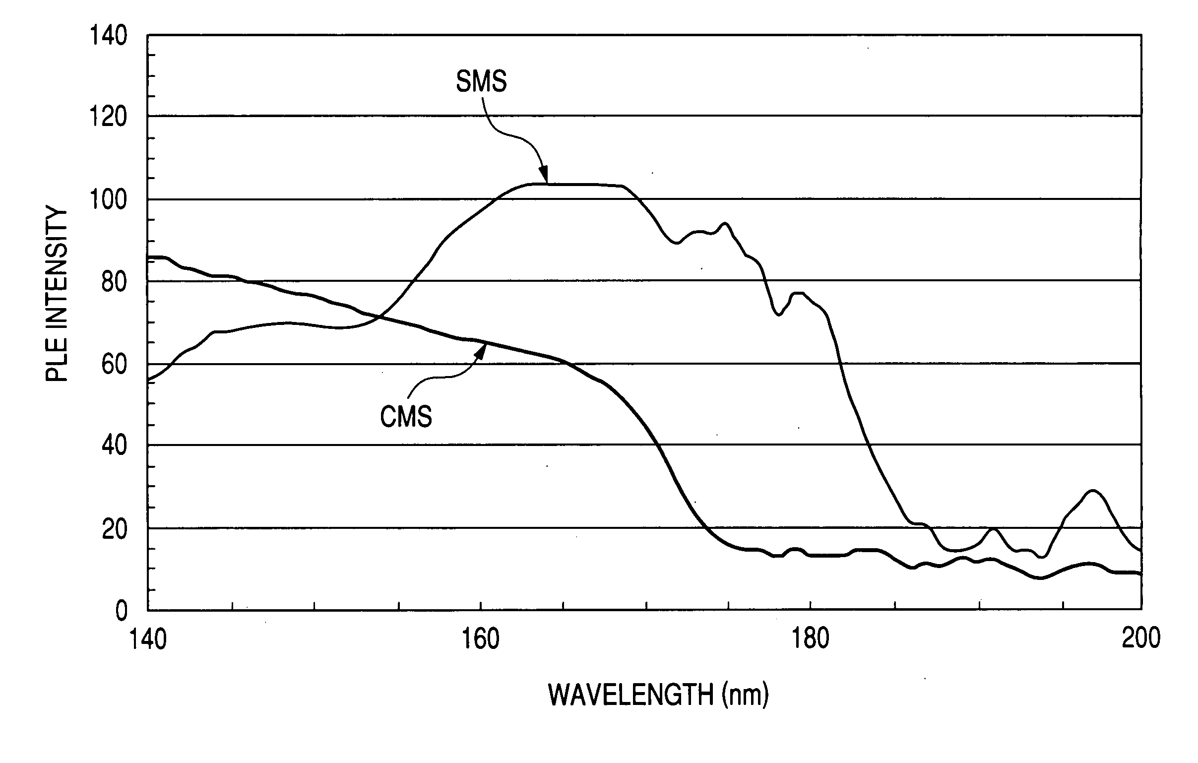
[0028] The light emitting devices according to the present invention use the high-luminance Eu-activated silicate phosphors capable of efficiently emitting light upon excitation not only by light at a wavelength of 147 nm but also by light at a wavelength of 172 nm and thereby exhibit high luminance.
[0029] The light emitting devices according to the present invention use the Eu-activated silicate phosphors capable of efficiently emitting light with high color purity upon excitation not only by light at a wavelength of 147 nm but also by light at a wavelength of 172 nm and can thereby emit light satisfactorily.
[0030] The display devices according to the present invention include light emitting devices using the high-luminance Eu-activated silicate phosphor and / or high-color-purity Eu-activated silicate phosphor and can thereby produce a display with high luminance and / or a display with high color purity.

Problems solved by technology

BAM exhibits good properties in its light emission but is susceptible to deterioration.
Namely, BAM exhibits insufficient reliability, has a short life and thereby must have improved stability and a longer life.
CMS originally having a low availability of the Xe2 molecular line, however, does not sufficiently contribute to higher efficiency of the plasma display devices.
More specifically, CMS shows a low emission efficiency upon excitation by ultraviolet light at 172 nm and shows insufficient properties in its luminance, even if the amount of ultraviolet light at wavelengths of around 172 nm.

Method used


Image

  • Light emitting device
  • Light emitting device
  • Light emitting device

Examples


first embodiment

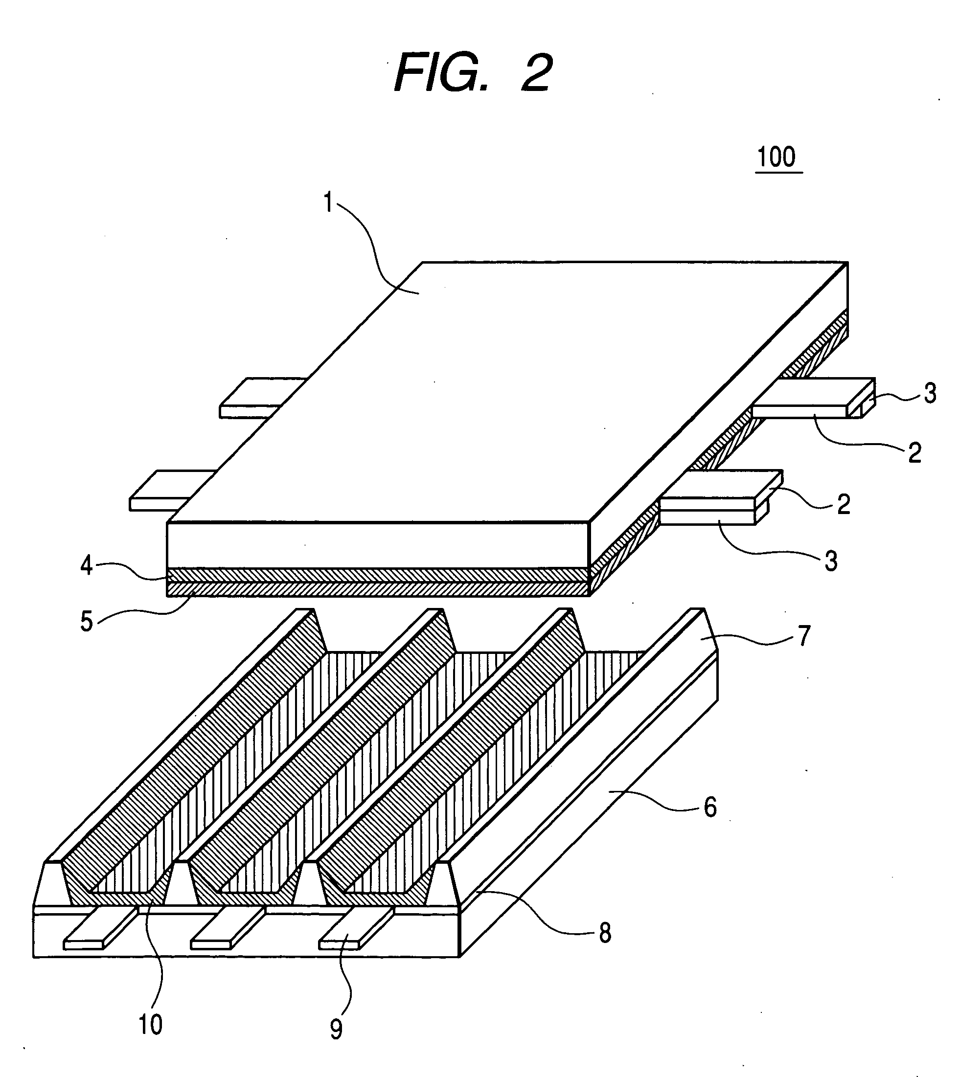
[0090] In the present embodiment, preparation of a phosphor, preparation of a plasma display panel using the phosphor, and preparation of an image display device using the plasma display panel will be sequentially illustrated with reference to the drawings.

[0091] (1) Preparation of Phosphor

[0092] A phosphor was synthetically prepared as a constitutional member of a plasma display panel according to the first embodiment of the present invention.

[0093] The resulting phosphor has a composition of Sr2.98MgSi2O8:Eu0.02.

[0094] The phosphor was prepared in the following manner. Initially, 4.399 g (29.80 mmol) of SrCO3, 0.962 g (10.00 mmol) of MgCO3, 1.202 g (20.00 mmol) of SiO2, 0.0352 g (0.10 mmol) of Eu2O3, and 0.392 g (4.00 mmol) of NH4Br as a flux were weighed, were fully mixed in an agate mortar, the resulting mixture was charged into a heat-stable vessel and was heated at 1250° C. in a reducing atmosphere for three hours.

[0095] The heated product was pulverized, was washed with ...

second embodiment

[0121] Initially, a material phosphor was synthetically prepared for the preparation of a plasma display panel according to the second embodiment of the present invention.

[0122] The prepared phosphor is a silicate phosphor (SMS) having a mole fraction of Mg slightly larger than the stoichiometric mole fraction (where b is 1 in the above formulae) and has a composition formula of Sr2.97Mg1.01Si2O8:Eu0.03. The actual composition formula of this phosphor is somewhat different from the composition formula just mentioned above, and the actual mole fraction typically of Sr is somewhat smaller than that in the compositional formula, since the mole fraction of Mg is larger than the stoichiometric mole fraction.

[0123] The phosphor was prepared in the following manner. Initially, 4.385 g (29.70 mmol) of SrCO3, 0.972 g (10.10 mmol) of MgCO3, 1.202 g (20.00 mmol) of SiO2, 0.0528 g (0.15 mmol) of Eu2O3, and 0.392 g (4.00 mmol) of NH4Br as a flux were weighed, were fully mixed in an agate morta...

third embodiment

[0132] Initially, a material phosphor was synthetically prepared for the preparation of a plasma display panel as the third embodiment of the present invention. The prepared phosphor is a silicate phosphor (SMS) having a mole fraction of Si larger than the stoichiometric mole fraction (where c is 1 in the above formulae) and has a composition formula of Sr2.99MgSi2.1O8.2:Eu0.01. The actual composition formula is somewhat different from the composition formula just mentioned above, and the actual mole fractions typically of Sr and Mg are somewhat smaller than the above composition, since the mole fraction of Si is larger than the stoichiometric mole fraction.

[0133] The phosphor was prepared in the following manner. Initially, 4.414 g (29.90 mmol) of SrCO3, 0.962 g (10.00 mmol) of MgCO3, 1.262 g (21.00 mmol) of SiO2, 0.0176 g (0.050 mmol) of Eu2O3, and 0.392 g (4.00 mmol) of NH4Br as a flux were weighed, were fully mixed in an agate mortar, the resulting mixture was charged into a he...


PUM


Abstract

A blue-emitting phosphor is optimized by controlling mole fractions typically of Mg and Si in Sr3-eMgbSi2cO8d:Eue or by further including an optimal amount of at least one additional component such as Ba or Ca. The resulting phosphor exhibits a higher brightness and a higher color purity upon excitation by ultraviolet light emitted as a result of discharge of xenon gas. The optimized phosphor is incorporated into light emitting devices such as lamps and PDPs, and further into display devices.

Description

CLAIM OF PRIORITY [0001] The present application claims priority from Japanese application serial no. 2005-19242, filed on Jan. 27, 2005, which further claims priority from Japanese application serial no. 2004-157036, filed on May. 27, 2004, the contents of which are hereby incorporated by the reference into this application. FIELD OF THE INVENTION [0002] The present invention relates to light emitting devices such as tubular or flat-panel fluorescent lamps or plasma display panels containing phosphors, typically EU-activated silicate phosphors, being excited by the action of ultraviolet light, typically vacuum ultraviolet light, to thereby emit light. It also relates to image display devices (hereinafter briefly referred to as display devices) using the light emitting devices. BACKGROUND OF THE INVENTION [0003] Demands have been increasingly made to reduce the thickness of display devices such as television sets and personal computer monitors for saving spaces. As such display devi...

Claims


Application Information

Patent Timeline
IPC IPC(8): C09K11/59C09K11/77H01J11/22H01J11/24H01J11/34H01J11/42H01J11/50H01J29/20H01J61/44
CPCC09K11/7734H01J61/44H01J11/42H01J11/12C09K11/77342
Inventor OAKU, HITOSHIOKAZAKI, CHOICHIROSHIIKI, MASATOSHI
Owner HITACHI LTD
Learn More