Flexible ceramic gasket for SOFC generator

a ceramic gasket and generator technology, applied in the field of composite positioning gaskets, can solve the problems of not solving the problem completely, increasing costs, and reducing the open end of the fuel cell located in the combustion chamber, and achieve the effect of effective absorption of mechanical and thermal loads and low cost production

Inactive Publication Date: 2005-12-01
SIEMENS ENERGY INC
View PDF15 Cites 34 Cited by
  • Summary
  • Abstract
  • Description
  • Claims
  • Application Information

AI Technical Summary

Benefits of technology

[0012] The compliant gasket, even when later baked / cured / sintered effectively absorbs mechanical and thermal loads induced by differential thermal expansion of the SOFC cells and the adjacent structures during generator operation, and maintains the important range of allowable pressure drop which has now been found in this environment to be between about 0.25-2.0 inches of water, to control spent fuel permeation through the gasket. Additionally, the simple fabrication of the fuel cell positioning gasket makes it ideal for low cost production. A lower positioning board if used, can be of the same construction or standard stiff board construction. The fuel cells can be closed or open ended, tubular or of flattened design. Thus, this provides a non seal-less design.

Problems solved by technology

In some instances, the open end of the fuel cell, located in the combustion chamber, was vulnerable to reduction by spent fuel.
Originally, this was solved by Zafred et al., in U.S. Pat. No. 6,221,522 B1, by utilizing open fuel cell end sleeves, but this added to costs and did not completely solve the problem.
However, inadequate sealing tended to cause some fuel and temperature mal-distribution.
Also, differential axial thermal expansion between the cells and the positioning boards, could lead to cells “grabbing” the boards during generator shutdowns and potentially breaking them.
Additionally, the use of initially stiff positioning boards required 100% location mapping using a very expensive laser mapping technique which generates a series of XY coordinates for each cell position.

Method used


Image

  • Flexible ceramic gasket for SOFC generator
  • Flexible ceramic gasket for SOFC generator
  • Flexible ceramic gasket for SOFC generator

Examples


example

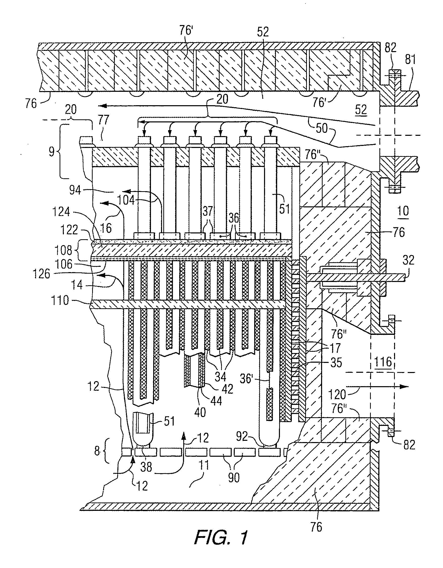
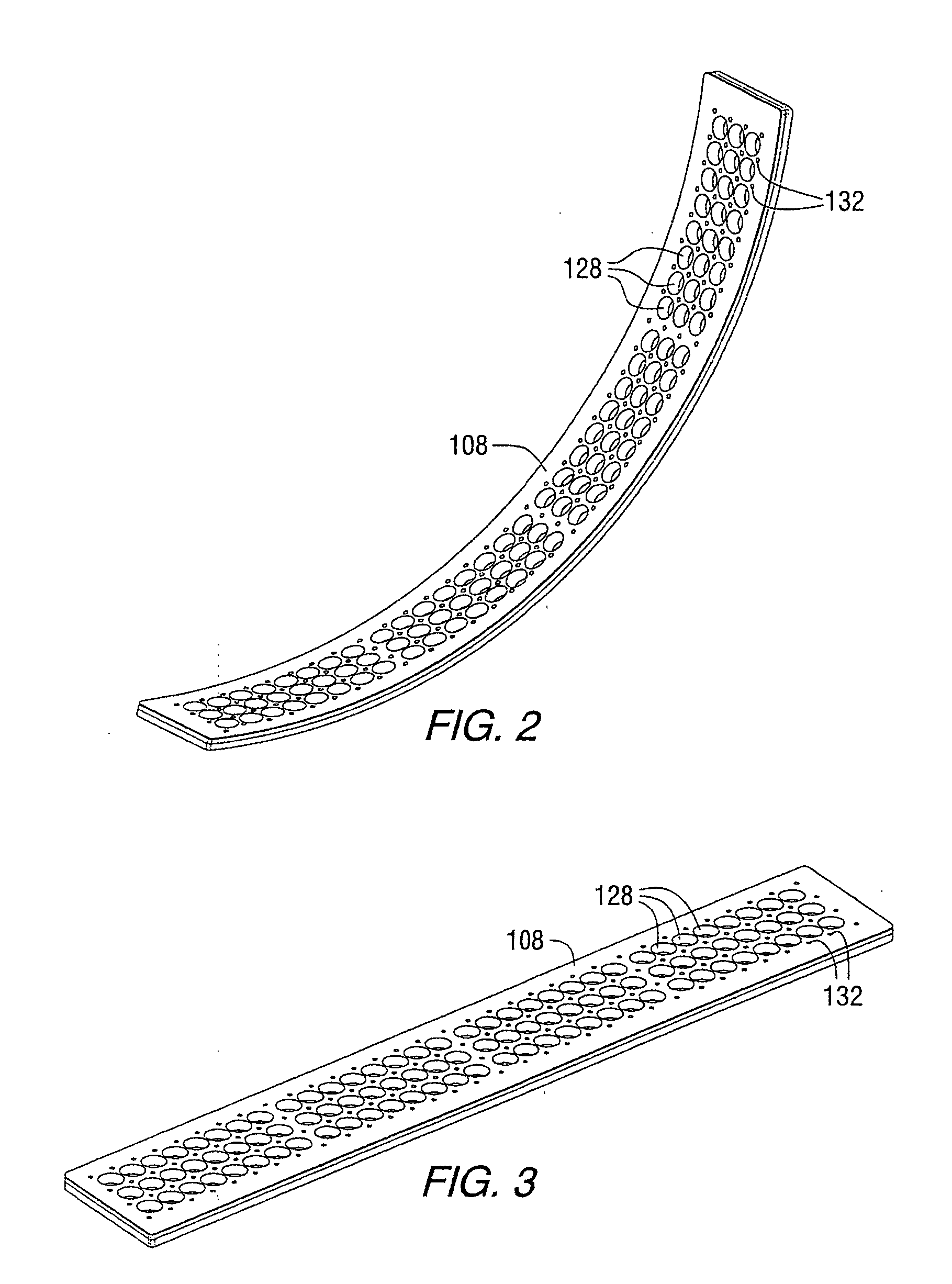
[0032] Prototypes of two potential gasket positioning board styles with square-pitched 3×8 hole arrays were made. The first was a pillow type gasket, with undersized holes for the cells punched out, then sewn with high-temperature ceramic thread to consolidate the gasket composite and prevent unraveling. The second was a quilted gasket, with cell holes cut using a laser. Both would be useful and accomplish all objectives of the invention, especially when the top would be impregnated with catalytic nickel oxide. To control pressure drop through the gasket, a number of parameters can be varied to optimize the consistency and the porosity of the matrix. Gas permeability can be controlled by using low-density ceramic fiber blankets or medium density papers or felts. The preferred method of fabrication consists in stitching a 3×8 hole pattern by the continuous intertwining of thin ceramic thread through the gasket thickness, relying on the uniformity of the gasket permeability rather tha...


PUM

PropertyMeasurementUnit
temperaturesaaaaaaaaaa

Abstract

A solid oxide fuel cell generator (10) contains stacks of hollow axially elongated fuel cells (36) having an open top end (37), an oxidant inlet plenum (52), a feed fuel plenum (11), a combustion chamber (94) for combusting reacted oxidant/spent fuel; and, optionally, a fuel recirculation chamber (106) below the combustion chamber (94), where the fuel recirculation chamber (94) is in part defined by semi-porous fuel cell positioning gasket (108), all within an outer generator enclosure (8), wherein the fuel cell gasket (108) has a laminate structure comprising at least a compliant fibrous mat support layer and a strong, yet flexible woven layer, which may contain catalytic particles facing the combustion chamber, where the catalyst, if used, is effective to further oxidize exhaust fuel and protect the open top end (37) of the fuel cells.

Description

GOVERNMENT CONTRACT [0001] The Government of the United States of America has rights in this invention pursuant to Contract No. DE-FC26-97FT34139, awarded by the U.S. Department of Energy.FIELD OF THE INVENTION [0002] The invention relates to novel composite positioning gaskets used to separate the combustion chamber of a solid oxide electrolyte fuel cell generator, hereinafter “SOFC generator”, from the other regions of the SOFC generator, such as the recirculation zone or stack region. BACKGROUND OF THE INVENTION [0003] High temperature, solid oxide electrolyte fuel cell generator apparatus and fuel cell configurations are well known, and taught, for example, in U.S. Pat. No. 4,395,468 (Isenberg). There, feed fuel, either H2+CO, or previously reformed natural gas, is fed into the apparatus at one end and flows parallel to exterior fuel electrode surfaces of elongated tubular fuel cells. Spent fuel is combusted with spent oxidant in a separate combustion chamber and then exits the ...

Claims


Application Information

Patent Timeline
Patent Type & Authority Applications(United States)
IPC IPC(8): H01M2/08H01M8/02H01M8/04H01M8/06H01M8/12H01M8/24
CPCH01M8/0276H01M8/0282H01M8/04089H01M8/04097Y02E60/525H01M8/1246H01M8/243Y02E60/521H01M8/0662Y02E60/50Y02P70/50H01M8/2483
Inventor ZAFRED, PAOLOPREVISH, THOMAS
Owner SIEMENS ENERGY INC
Why Eureka
Try Eureka