Supercharge Your Innovation With Domain-Expert AI Agents!

Programmable power supply

a power supply and programmable technology, applied in the field of power supplies, can solve the problems of insufficient power, large external power supply, and difficulty in providing the necessary power curve for rechargeable batteries, and achieve the effect of small form factor power supply, high efficiency of conversion and regulation, and high efficiency

Inactive Publication Date: 2005-12-01
COMARCO WIRELESS TECH
View PDF44 Cites 13 Cited by
  • Summary
  • Abstract
  • Description
  • Claims
  • Application Information

AI Technical Summary

Benefits of technology

"The present invention provides an improved small form factor power supply that is resistant to liquids and programmable to supply power for a variety of different devices. The power supply includes a transformer and a controller that can alter the phase of the square wave signals to produce the desired output DC voltage and current. The secondary circuit is positioned on the core of the primary circuit so that the secondary circuit coil is at a summing point on the core of the first and second primary circuit coils. The system minimizes dissipation of heat permitting the entire power supply to be mounted within a high impact plastic container. The improved transformer core maximizes the cross-sectional area of the transformer legs to require fewer windings, which reduces the area of a layer of a circuit board. The power supply is programmable to provide power to different portable electronic devices and can be adapted to support a variety of devices simultaneously."

Problems solved by technology

Smaller power supplies do exist but frequently they lack sufficient power to charge new batteries such as nickel hydride batteries.
Further, the external power supply is bulky and may not be readily carried in typical cases for such notebook and sub-notebook computers.
In addition, conventional power supplies often have difficulty providing the necessary power curve to recharge batteries that have been thoroughly discharged.
While it has long been known to be desirable to reduce the size and weight of the power supply, this has not been readily accomplished.
Many of the components such as the transformer core are bulky and have significant weight.
Further, such power supplies may need to be able to provide DC power of up to seventy-five watts, thereby generating substantial heat.
Due to the inherent inefficiencies of power supplies, this results in substantial heat being generated within the power supply.
Reduction of the volume, weight and heat are all critical considerations for a power supply in this type of application and cannot be readily accomplished.
Therefore, users need multiple power supplies, which consumes space and increases unnecessary weight.

Method used


Image

  • Programmable power supply
  • Programmable power supply
  • Programmable power supply

Examples


Embodiment Construction

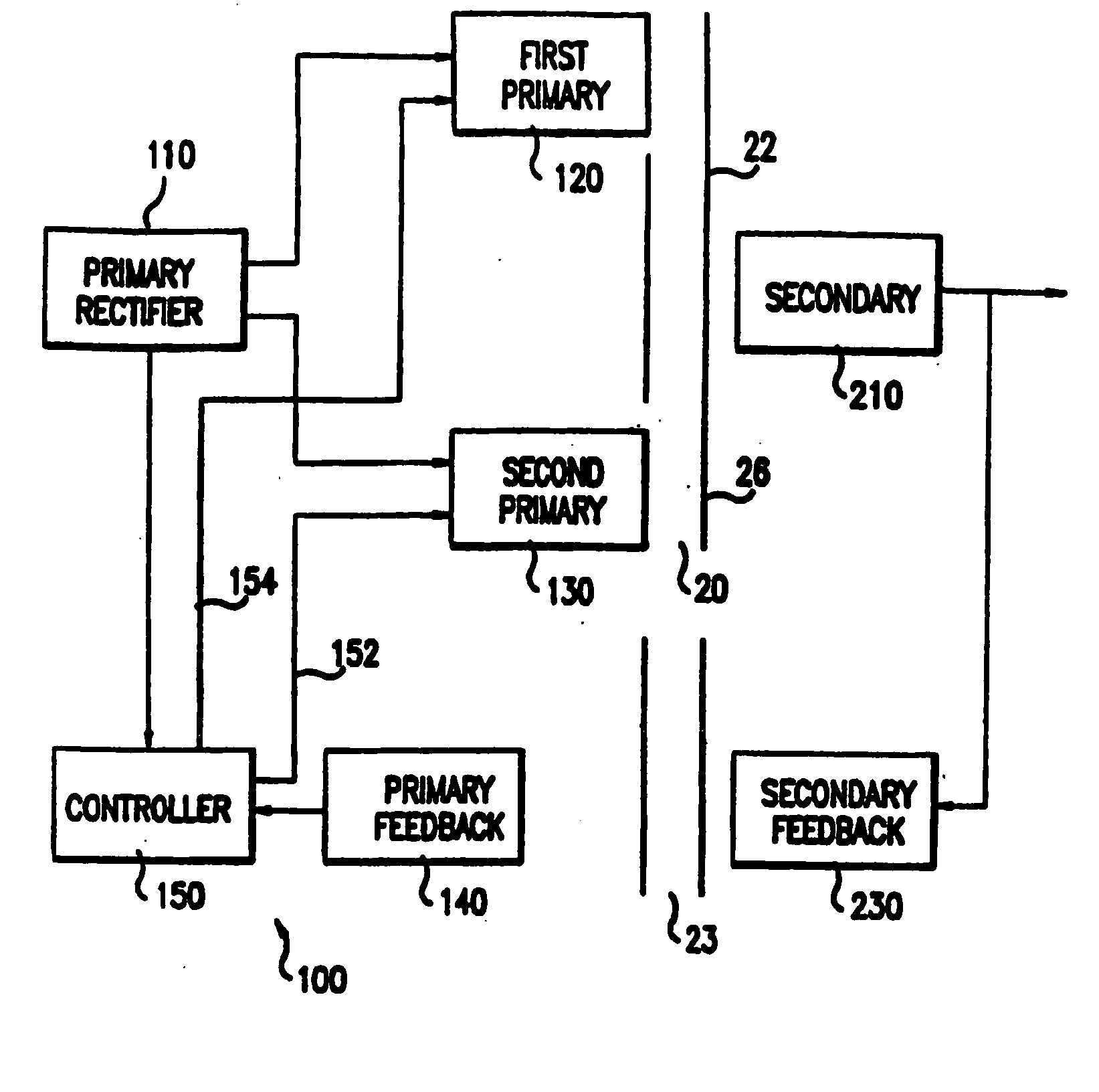
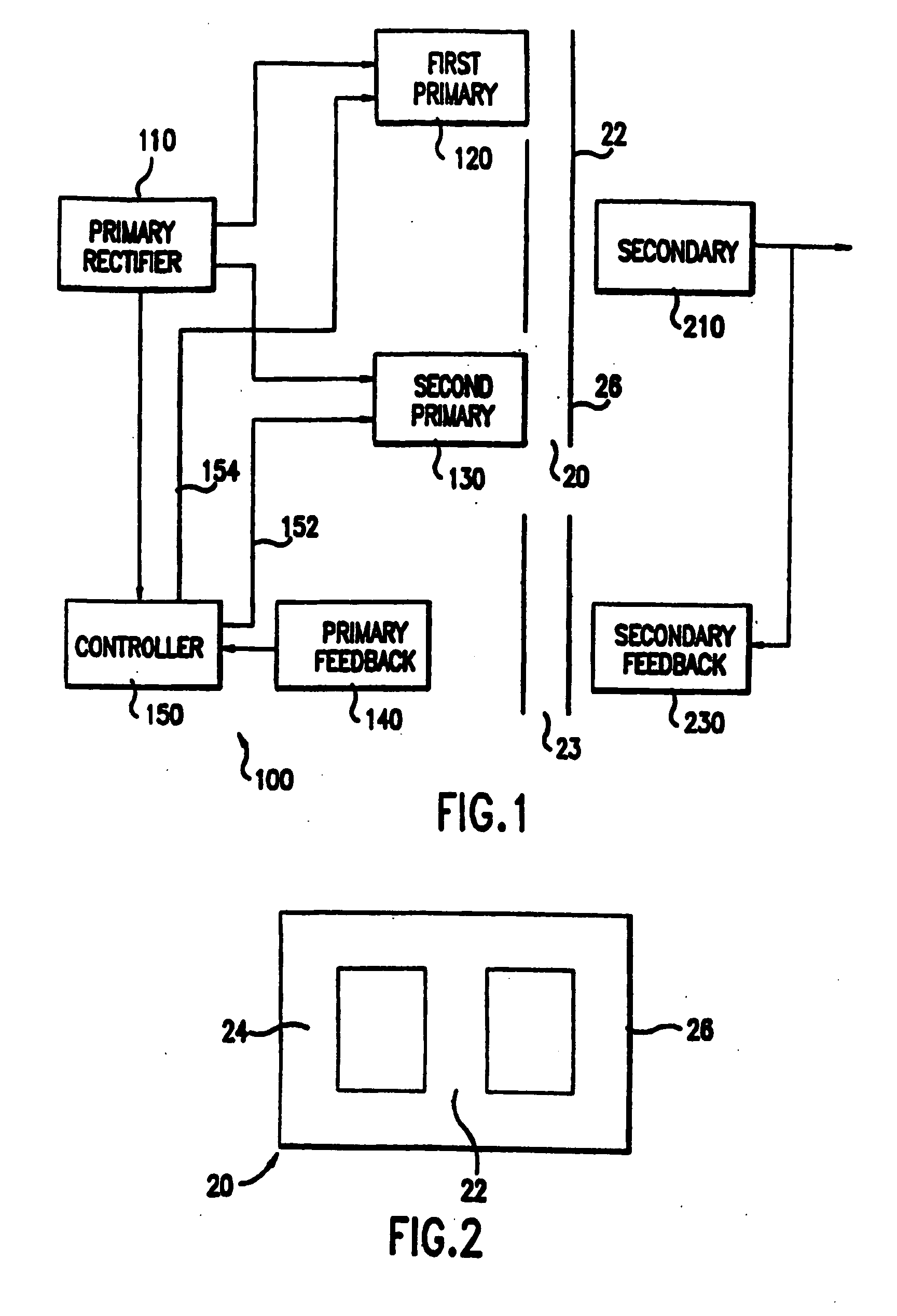
[0065] As shown in the drawings for purposes of illustration, embodiments of the present invention are directed to an improved small form factor power supply. In preferred embodiments of the present invention, the small form factor power supply is packaged in a small volume and produces over 75 watts of power with temperatures below 140° F. Preferred embodiments are used to power portable computers. However, it will be recognized that further embodiments of the invention may be used with other electronic devices, such as computer peripherals, audio and video electronics, portable telephone equipment and the like.

[0066] Other embodiments of the present invention are more generally directed to a power supply which is capable of providing power to any selected one of a number of electronic devices in response to a programming signal. Each of the electronic devices is adapted for receiving input power at either a set operational voltage or a set operational current. The programming sig...


PUM


Abstract

A power supply system includes a power source and a control circuit. The power source provides DC power. A control circuit, which is remote to the power source, receives the DC power and provides a first DC power signal to an electronic device. The control circuit includes an active component to provide at least one of a voltage control output or a current control output to the power source to regulate the DC power. A power supply system includes a power source and a control circuit. The control circuit is remote to the power source, receives the DC power, and provides the DC power to an electronic device. The control circuit includes a microprocessor to provide at least one of a voltage control output and a current control output to the power source to regulate the DC power.

Description

RELATED APPLICATIONS [0001] This application is a continuation-in-part application of utility application Ser. No. 09 / 310,461 filed on May 12, 1999, which is a continuation-in-part application of utility application Ser. No. 09 / 148,811 filed on Sep. 4, 1998, which is a continuation-in-part of utility application Ser. No. 08 / 767,307 filed Dec. 16, 1996, which is a continuation-in-part application of utility application Ser. No. 08 / 567,369 filed Dec. 4, 1995, now U.S. Pat. No. and claims priority of provisional application Ser. No. 60 / 002,488 filed Aug. 17, 1995, and is also a continuation-in-part application of utility application Ser. No. 08 / 233,121 filed Apr. 26, 1994, now U.S. Pat. No. 5,479,331 issued Dec. 26, 1995.NOTICE OF COPYRIGHTS [0002] A portion of the disclosure of this patent document contains material which is subject to copyright protection. The copyright owner has no objection to the facsimile reproduction by anyone of the patent disclosure, as it appears in the Unite...

Claims


Application Information

Patent Timeline
Patent Type & Authority Applications(United States)
IPC IPC(8): G06F1/26H01R13/24H01R13/66H02J7/00H02J7/02H02M1/00H02M1/42H02M3/00H02M3/28H02M3/337H02M3/338H05K1/16
CPCG06F1/26Y02B40/90H01R13/24H01R13/6675H01R2201/16H01R2201/24H02J7/0008H02J7/0068H02J7/022H02M1/4258H02M3/00H02M3/156H02M3/28H02M3/33507H02M3/33523H02M3/3372H02M3/3378H02M3/3382H02M3/3387H02M7/003H05K1/0203H05K1/0262H05K1/029H05K1/16H05K1/165H05K2201/086H05K2201/09063Y02B70/126H01F2027/2819H02J7/00041H02J7/02H02J2207/20H02J7/00047Y02B40/00Y02B70/10H02M3/003
Inventor LANNI, THOMAS W.
Owner COMARCO WIRELESS TECH
Features
  • R&D
  • Intellectual Property
  • Life Sciences
  • Materials
  • Tech Scout
  • Unparalleled Data Quality
  • Higher Quality Content
  • 60% Fewer Hallucinations
Learn More