
Electrosurgical instrument and method of use

a technology of electrosurgical instruments and electrodes, applied in the field of medical devices, can solve problems such as difficult sealing of tissues, and achieve the effects of uniform ohmic heating of tissues, effective welding of tissues, and uniform current flow

Inactive Publication Date: 2005-12-01
SURGRX
View PDF99 Cites 305 Cited by
  • Summary
  • Abstract
  • Description
  • Claims
  • Application Information

AI Technical Summary

Benefits of technology

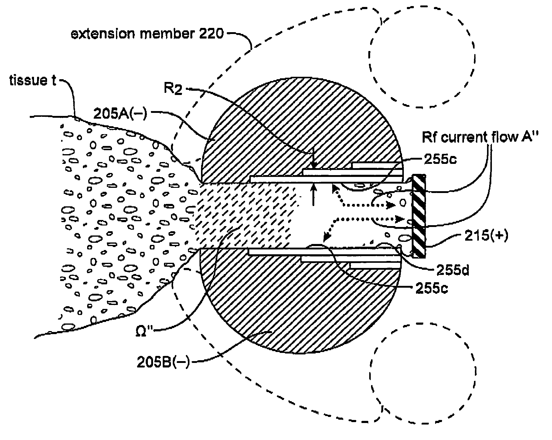
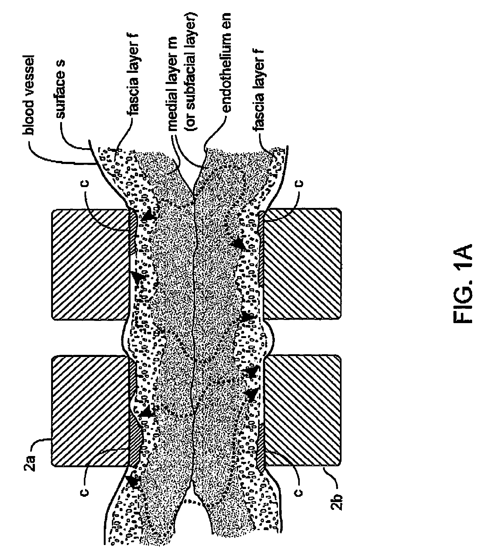
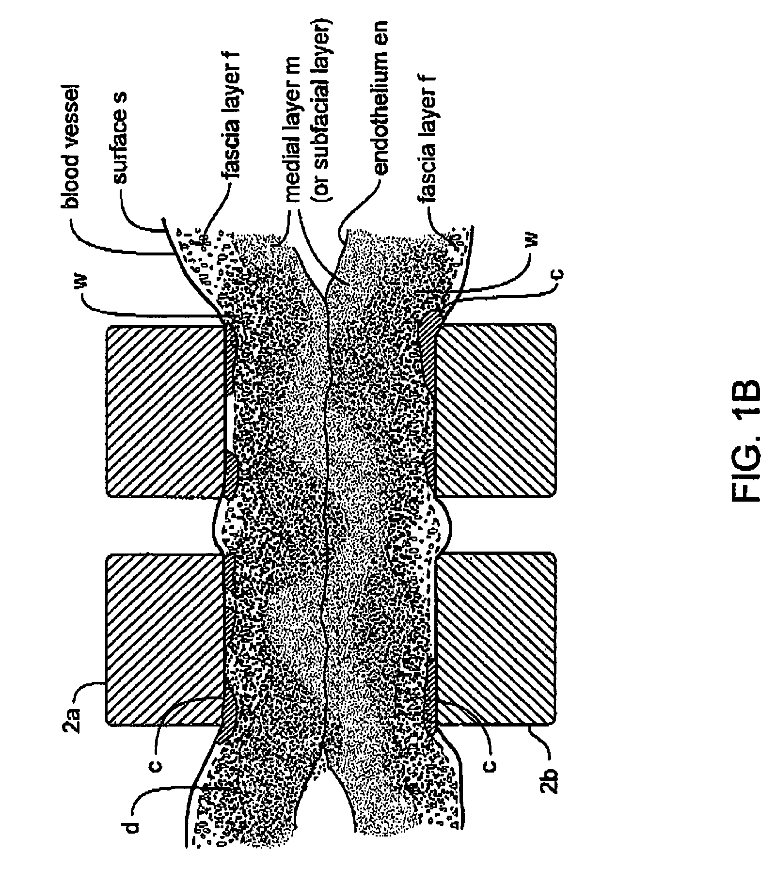
[0010] One aspect of the present invention provides an instrument and working end that is capable of transecting tissue and highly compressing tissue to allow for controlled Rf energy delivery to the transected tissue margins. The objective of the invention is to effectively weld tissues that have thick fascia layers or other layers with non-uniform fibrous content. Such tissues are difficult to seal since the fascia layers can prevent uniform current flow and uniform ohmic heating of the tissue.
[0012] In order to create an effective weld in a tissue volume dominated by the fascia layers, it has been found that are factors to be considered. It is desirable to create a substantially even temperature distribution across the targeted tissue volume to create a uniform weld or seal. Fibrous tissue layers (i.e., fascia) conduct Rf current differently than adjacent less-fibrous layers, and it is believed that differences in extracellular fluid content in such adjacent tissues also contribute greatly to the differences in ohmic heating. It has been found that by applying very high compressive forces to fascia layers and underlying non-fibrous layers, the extracellular fluids migrate from the site to collateral regions. Thus, the compressive forces can make resistance more uniform regionally within the engaged tissue.

Problems solved by technology

Such tissues are difficult to seal since the fascia layers can prevent uniform current flow and uniform ohmic heating of the tissue.

Method used


Image

  • Electrosurgical instrument and method of use
  • Electrosurgical instrument and method of use
  • Electrosurgical instrument and method of use

Examples


Embodiment Construction

[0034] 1. Type “A” Working End for Transecting Tissue and Sealing the Transected Margins. Referring to FIG. 2A, the working end 100 of an exemplary Type “A” embodiment is shown that is adapted for transecting and welding at least one transected tissue margin along a targeted track or path p in tissue, such as lung portion, in an open or endoscopic procedure. The working end 100 has first and second elongate guide members or guide-track members indicated at 105A

[0035] and 105B that are substantially flexible wire-type elements carried at distal end 108 of an introducer member 110 extending from a proximal handle (not shown). In this Type “A” embodiment, the guide members (or jaws) 105A and 105B extend along a central longitudinal axis 115 and provide multiple functionality: (i) to place over or about a target path p in tissue that is to be transected; (ii) to thereafter guide the terminal portion 118 of an extension member 120 carrying an electrode cutting element 122 along the targ...


PUM


Abstract

An embodiment of a method of the invention provides a method for welding tissue comprising providing a tissue welding device having first and second tissue engaging surfaces with at least one surface including an electrode surface that defines a plurality of surface portions having different resistances to electrical current flow therethrough. A target tissue volume is engaged with the tissue engaging surfaces. Rf energy is delivered to the target volume to create a substantially even temperature distribution across at least a portion of the target tissue volume to substantially uniformly weld at least a portion of the target tissue volume.

Description

CROSS-REFERENCES TO RELATED APPLICATIONS [0001] This application is a continuation-in-part of co-pending U.S. patent application Ser. Nos. 10 / 351,449 filed on Jan. 22, 2003, entitled Electrosurgical Instrument and Method of Use (Attorney Docket No. 021447-000540US); Ser. No. 10 / 032,867 filed on Oct. 22, 2001, entitled Electrosurgical Jaw Structure for Controlled Energy Delivery (Attorney Docket No. 021447-000500US); and Ser. No. 09 / 982,482 filed on Oct. 18, 2001, entitled Electrosurgical Working End for Controlled Energy Delivery (Attorney Docket No. 021447-000400US), the full disclosures of which are incorporated herein by reference.BACKGROUND OF THE INVENTION [0002] 1. Field of the Invention [0003] Embodiments of the invention relates to medical devices and more particularly relates to the working end of an electrosurgical instrument that is adapted for sealing or welding tissue that is engaged between paired jaw members. More specifically, an embodiment of the invention relates t...

Claims


Application Information

Patent Timeline
Patent Type & Authority Applications(United States)
IPC IPC(8): A61B18/14
CPCA61B2018/00619A61B18/1442
Inventor TRUCKAI, CSABASHADDUCK, JOHNSTRUL, BRUNOBAKER, JAMES A.
Owner SURGRX
Learn More