Fusion/coagulation work fixing agent and machining method using the same
a technology of fusion/coagulation work and fixing agent, which is applied in the direction of manufacturing tools, metal-working machine components, optical surface grinding machines, etc., can solve the problems of low workability of machining operation, low purity of paraffin used in the conventional method, etc., and achieve the effect of improving the workability of machining method
- Summary
- Abstract
- Description
- Claims
- Application Information
AI Technical Summary
Benefits of technology
Problems solved by technology
Method used
Image
Examples
first embodiment
[0250] A first embodiment of the invention is explained below with reference to the drawings.
[0251] The fusion / coagulation work fixing agent is used to fix a work (an object to be machined) on a fixing table in the machining operation. According to this embodiment, a sapphire substrate of an optical semiconductor (such as a blue emission diode) is used as a work and is subjected to superfine surface grinding.
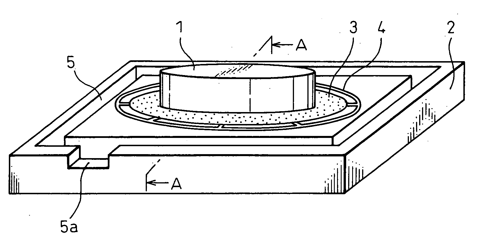
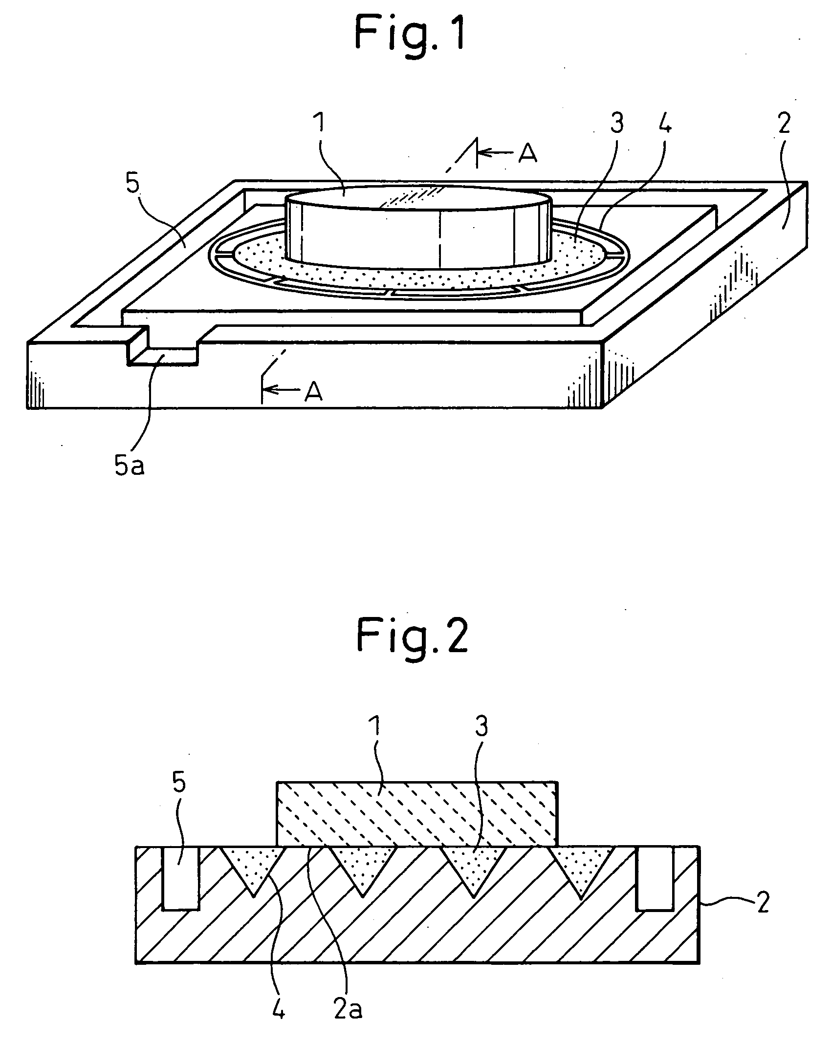
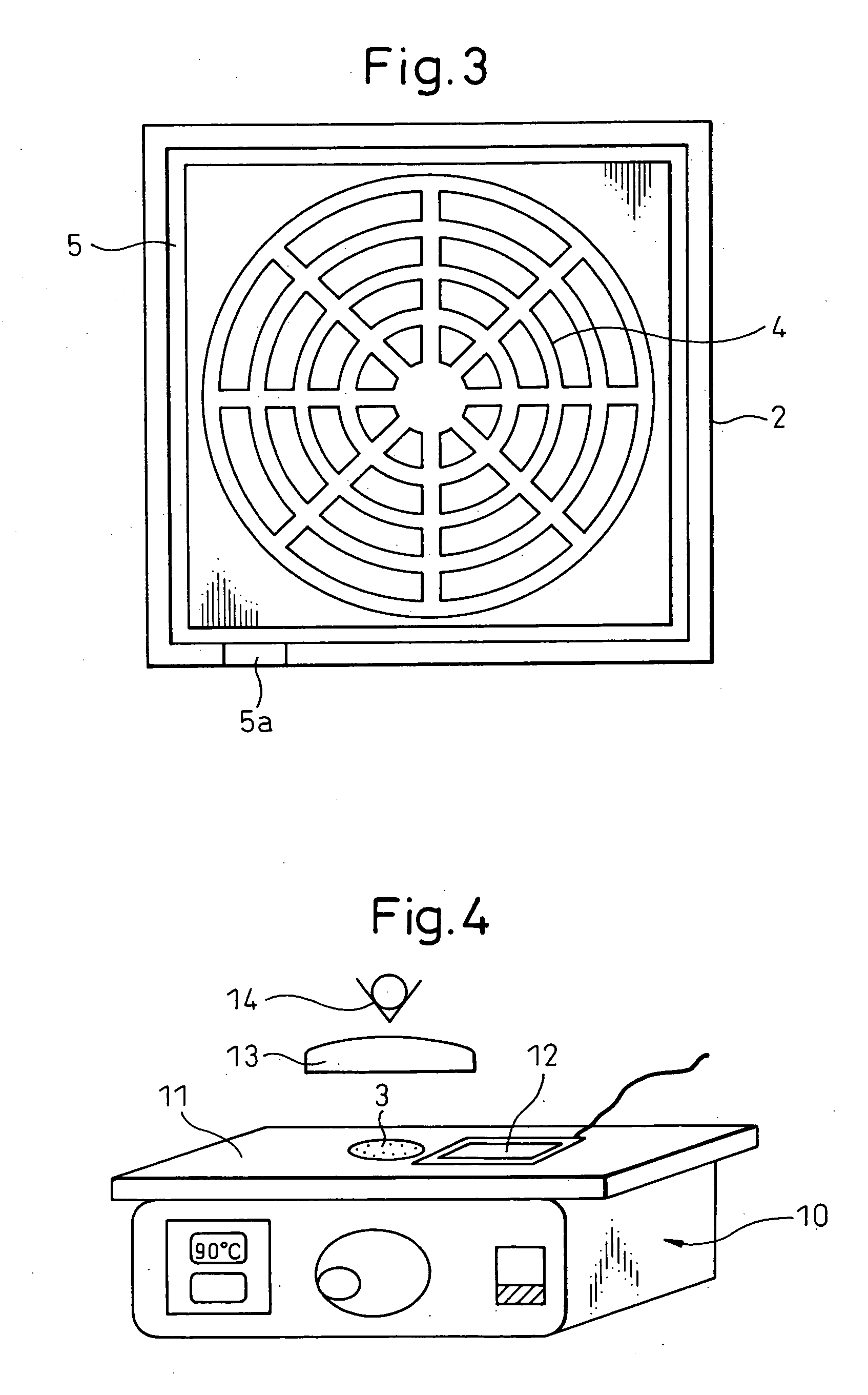
[0252] FIGS. 1 to 3 are diagrams showing a superfine surface grinding method according to this embodiment. A work 1 is a disk-like sapphire substrate 50 mm diameter and 0.3 mm thick. A grooved fixing table 2 is formed of a magnetic iron material (for example, JIS (Japanese Industrial Standard)—S50C, JIS-SUS 430 having a rectangular contour.
[0253] A groove 4 into which a work fixing agent 3 is injected is formed on the surface of the fixing table 2. The groove 4 is formed in the shape of a combination of a plurality of concentric circles and a plurality of radial straight line...
second embodiment
[0274] The second embodiment represents a case in which the work fixing agent according to the invention is used for the wire electric discharge machining. FIG. 6 shows a wire electric discharge machining method according to the second embodiment. The work 1 is cubically formed of a steel material (JIS-S50C) 100 mm wide, 100 mm deep and 100 mm tall.
[0275] In the wire electric discharge machining process according to the second embodiment, as shown in FIG. 7, the wire discharge machining is conducted along a predetermined machining track from the machining start point 1a toward the machining stop point 1b of the work 1 (primary machining).
[0276] Specifically, with the coolant (water) filled around the work 1, the work 1 and the wire 30 are impressed with a high-frequency voltage from a machining power supply 31 connected by terminals 31a, 31b. At the same time, a work table (not shown) on which the work 1 is placed is moved along the predetermined machining track thereby to conduct...
third embodiment
[0292] The third embodiment of the invention is explained below with reference to the drawings. FIG. 10 is a perspective view of the work fixing table 101 and the work 104 according to the third embodiment. The manner in which the work 104 is fixed and machined is described later.
[0293] The work fixing table 101 is made of a steel material JIS-S50C and parallelepiped in shape having side lengths of 100 mm each and a thickness of 15 mm. A rectangular coolant path 106 which is a groove for supplying the coolant 107a such as water supplied from the coolant supply port 107 is formed on the outermost peripheral portion of the work fixing surface 102. Further, an exhaust port 106a to discharge the coolant from the coolant path 106 is formed on the outer wall of the coolant path 106.
[0294] A work contact surface 102a smaller than the work fixing surface 102 is formed to the size of 80 mm×80 mm inside the coolant path 106 of the work fixing surface 102. The work contact surface 102a is fo...
PUM
| Property | Measurement | Unit |
|---|---|---|
| Temperature | aaaaa | aaaaa |
| Temperature | aaaaa | aaaaa |
| Temperature | aaaaa | aaaaa |
Abstract
Description
Claims
Application Information
 - R&D
- Intellectual Property
- Life Sciences
- Materials
- Tech Scout
- Unparalleled Data Quality
- Higher Quality Content
- 60% Fewer Hallucinations
Browse by: Latest US Patents, China's latest patents, Technical Efficacy Thesaurus, Application Domain, Technology Topic, Popular Technical Reports.
© 2025 PatSnap. All rights reserved.Legal|Privacy policy|Modern Slavery Act Transparency Statement|Sitemap|About US| Contact US: help@patsnap.com


