Eureka AIR delivers breakthrough ideas for toughest innovation challenges, trusted by R&D personnel around the world.

Optical information recording/reproduction medium recording method, recording/reproduction method, and reproduction method, recording device, recording/reproduction device, reproduction device, and optical information recording/reproduction medium

Inactive Publication Date: 2005-12-08
NEC CORP
View PDF6 Cites 32 Cited by
  • Summary
  • Abstract
  • Description
  • Claims
  • Application Information

AI Technical Summary

Benefits of technology

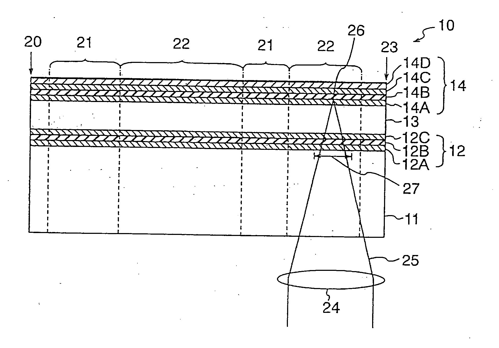
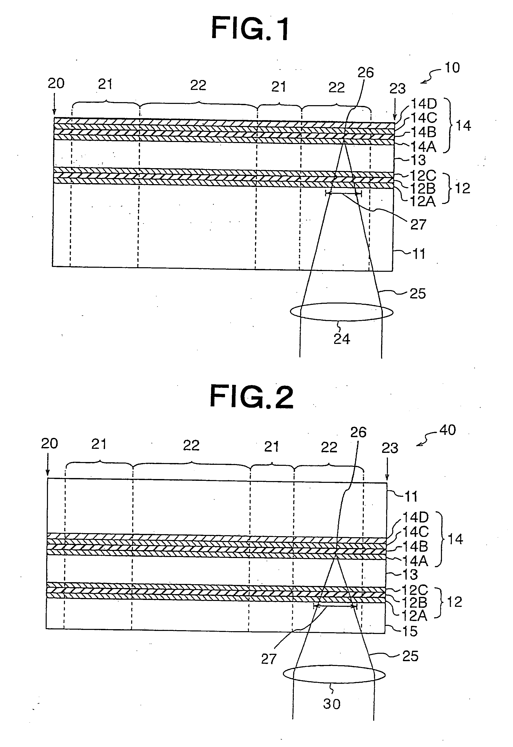
[0014] The recording layer management information of one recording layer is recorded in each of the recording management areas of the one recording layer and the other recording layer farther from the laser beam incident surface than the one recording layer. Thus, when recording or reproducing is performed on the other recording layer, the recording layer management information of the one recording layer can be quickly checked without shifting a focus of a laser beam to the one recording layer by a layer jumping operation. Additionally, when data is recorded and reproduced on and from the other recording layer, a laser beam of relatively high intensity passes through the one recording layer. Thus, a possibility of losing the recording layer management information due to data rewriting may be relatively high in the one recording layer. Accordingly, by recording the recording layer management information of the one recording layer on the other recording layer in which the rewriting is difficult to occur, it is possible to disperse risks of losing the recording layer management information.
[0027] According to the optical information recording and reproducing method, the recording method and the reproducing method of the invention, when the data recording or reproducing is performed on the one recording layer, the recording state as to whether data has been recorded or not on the other recording layer nearer the laser beam incident surface than the one recording layer is examined, and the laser beam output for the recording or reproducing is adjusted based on the recording state. Thus, it is possible to perform stable data recording and reproducing on the one recording layer. Moreover, according to the optical information recording device, the recording and reproducing device and the reproducing device, they can be constituted as devices which provide the aforementioned effects.

Problems solved by technology

However, in the optical disk of the write-once type or the rewritable type using the phase change recording film, the following problem has occurred in the case of multilayer.
However, in such an optical disk, because of using of a change in reflectance of the recording film for recording, the recording inevitably causes a change in transmittance of the recording film.
Thus, when recording is performed on the recording film of the side near the laser beam incident surface, a change occurs in intensity of a laser beam which reaches the recording film of the farther side, causing a problem of adversely affecting recording and reproducing on and from these recording films.
For example, irregular recording or recording loss occurs during recording, or reproduction failures occur during reproducing.
According to this method, however, when recording or reproducing is performed on an information recording medium having a plurality of recording layers, especially when recording or reproducing is performed not on a recording layer of a side nearest a laser beam incident surface but a recording layer of a farther side, unless management information is formed in the layer, a complex process of checking the management information by layer jumping and moving to a desired recording layer by interlayer jumping again is necessary for each recording or reproducing.
Thus, there is a drawback that the data recording or reproducing takes long time.

Method used


Image

  • Optical information recording/reproduction medium recording method, recording/reproduction method, and reproduction method, recording device, recording/reproduction device, reproduction device, and optical information recording/reproduction medium
  • Optical information recording/reproduction medium recording method, recording/reproduction method, and reproduction method, recording device, recording/reproduction device, reproduction device, and optical information recording/reproduction medium
  • Optical information recording/reproduction medium recording method, recording/reproduction method, and reproduction method, recording device, recording/reproduction device, reproduction device, and optical information recording/reproduction medium

Examples


embodiment 1

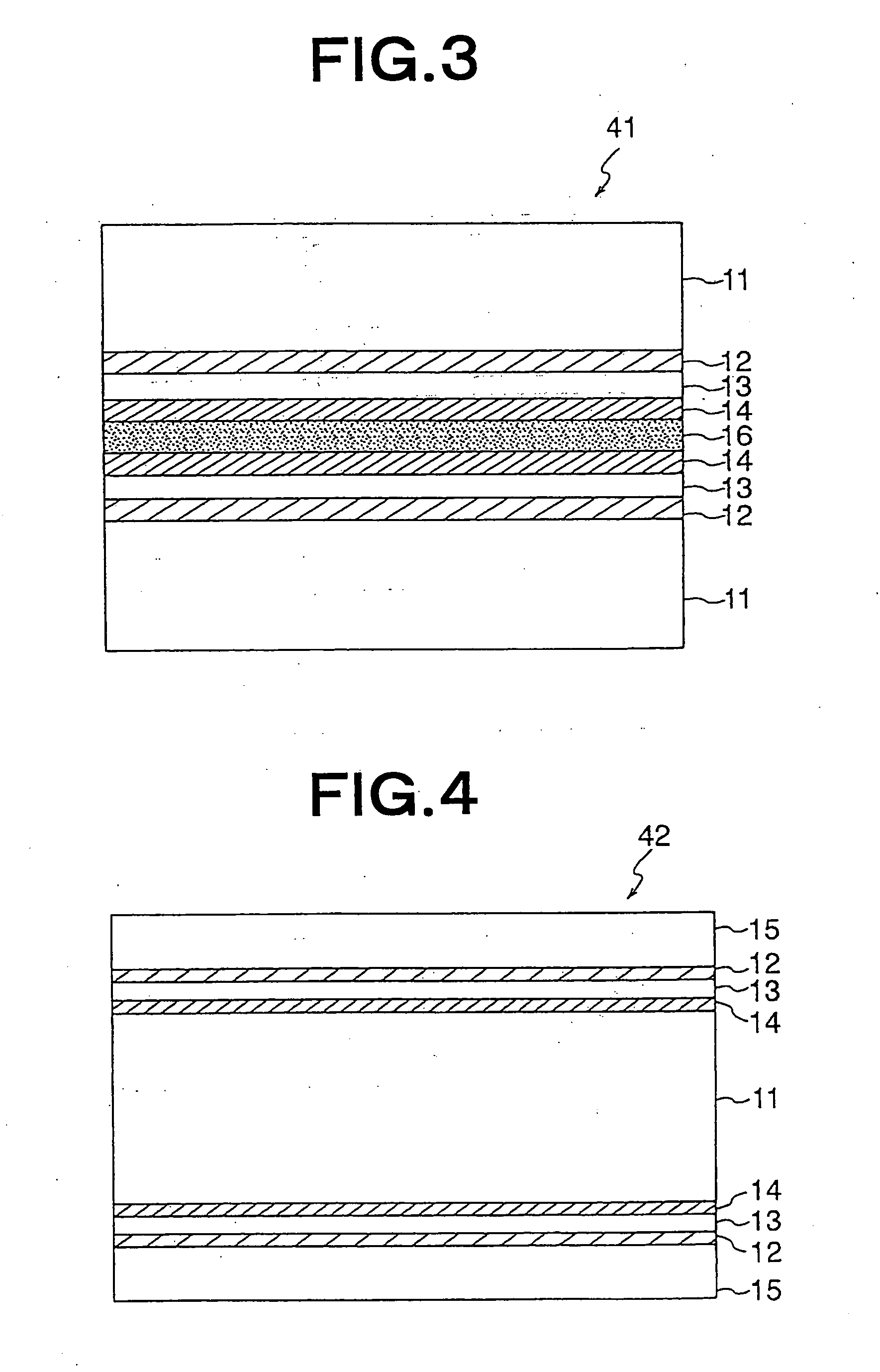
[0097]FIG. 8 is a sectional view showing a constitution of an optical information recording / reproducing medium of the embodiment. A medium 44 has a constitution in which two substrates having recording layers formed on surfaces are set to face each other and stuck together through an ultraviolet curing resin having a predetermined thickness.

[0098] That is, as a first substrate 17, a polycarbonate resin substrate having an outer diameter of 120 mm, an inner diameter of 15 mm, and a substrate thickness of 0.6 mm was used. For the first substrate 17, a substrate in which a wobbling groove 31 shown in FIG. 6 was formed beforehand by mastering was used. A shape of the wobbling groove 31 had a depth of 60 nm and a track pitch of 0.74 μm. The wobbling groove 31 was spiral and formed so as to achieve a wobbling frequency of 700 kHz when it was rotated from the inner periphery to the outer periphery of the first substrate 17 at a linear velocity of 3.9 m / sec. A radius 22 mm to 24 mm of the ...

embodiment 2

[0110] Reproducing was tried from the second recording layer 14 by using the medium 44 of the Embodiment 1, and the device 50 of the embodiment.

[0111] To begin with, data was recorded in the data recording area 22 of a radius 30 mm to 32 mm of the second recording layer 14. Next, data was recorded in the data recording area 22 of the radius 30.5 mm to 31.5 mm of the first recording layer 12. In this case, in accordance with the aforementioned procedure, information indicating that addresses (address 6ED90 hex to address 79BDF hex) allocated to the radius 30.5 mm to 31.5 mm of the first recording layer 12 had been recorded was recorded in the control area 21 of the second recording layer 14.

[0112] Subsequently, a host transmitted a command for performing reproducing in a position of the radius 31 mm of the data recording area 22 of the second recording layer 14. In accordance with the aforementioned procedure, the device 50 first performed reproducing in the control area 21 of the ...

embodiment 3

[0114] Recording was tried on the second recording layer 14 by using the medium 44 of the Embodiment 1, and the device 50 of the embodiment.

[0115] To begin with, data was recorded in the data recording area 22 of a radius 30 mm to 32 mm of the first recording layer 12. In this case, in accordance with the aforementioned procedure, information indicating that addresses (address 69680 hex to address 7E2DF hex) allocated to the radius 30 mm to 32 mm of the first recording layer 12 had been recorded was recorded in the control area 21 formed in the inner periphery of the first recording layer 12.

[0116] Subsequently, a host transmitted a command for performing recording in the radius 31.8 to 32.2 mm of the data recording area 22 of the second recording layer 14. In accordance with the aforementioned procedure, the device 50 first performed reproducing in the control area 21 of the second recording layer 14. The recording layer management information-reproducing circuit 109 recognized t...


PUM


Abstract

Optical information recording and reproducing medium 10 has two recording layers of first and second recording layers 12 and 14, from a laser beam incident surface side. In each control area 21, recording layer management information containing at least information indicating recording states of a plurality of areas into which the inside of data recording area 22 of each recording layer is divided is recorded. When recording or reproducing is performed on the second recording layer 14, the recording layer management information is checked, and a laser beam output is changed based on a recording state of an area corresponding to the first recording layer 12.

Description

TECHNICAL FIELD [0001] The present invention relates to a recording method, a recording and reproducing method, a reproducing method, a recording device, a recording and reproducing device, and a reproducing device for an optical information recording and reproducing medium, which perform data recording and reproducing by irradiation with a laser beam, and the optical information recording and reproducing medium. BACKGROUND ART [0002] An optical disk recording device (optical disk) using a laser beam has a high recording density and can perform large-capacity recording. Because of an operation in non-contact, the device allows high-speed accessing and its practical application as a large-capacity memory has progressed. The optical disk is classified into a read only type which allows only reproduction, a write-once type which allows only one recording operation at a user side, and a rewritable type which allows repeated recording operations at the user side. The read only type is us...

Claims


Application Information

Patent Timeline
IPC IPC(8): G11B7/00G11B7/0045G11B7/006G11B7/007G11B7/125
CPCG11B7/00456G11B7/0062G11B7/00736G11B7/24038G11B2007/0013
Inventor OKADA, MITSUYAIWANAGA, TOSHIAKISHIBATOKO, TAKEHARUTANABE, HIDEKIKUBOTA, MASASHINAKANO, MASAKISUGAYA, SATOSHI
Owner NEC CORP
Why Eureka
Eureka Blog
Learn More