Moisture data-acquiring device and image-forming apparatus

Inactive Publication Date: 2005-12-08
CANON KK
View PDF2 Cites 30 Cited by
  • Summary
  • Abstract
  • Description
  • Claims
  • Application Information

AI Technical Summary

Benefits of technology

[0008] The above conventional optical type of moisture-measuring device requires essentially optical parts such as a light source, a light detector, and a spectroscope or filter. Further, the optical type of

Problems solved by technology

Further, the optical type of moisture-measuring device can be affected by dust from t

Method used


Image

  • Moisture data-acquiring device and image-forming apparatus
  • Moisture data-acquiring device and image-forming apparatus
  • Moisture data-acquiring device and image-forming apparatus

Examples


example 1

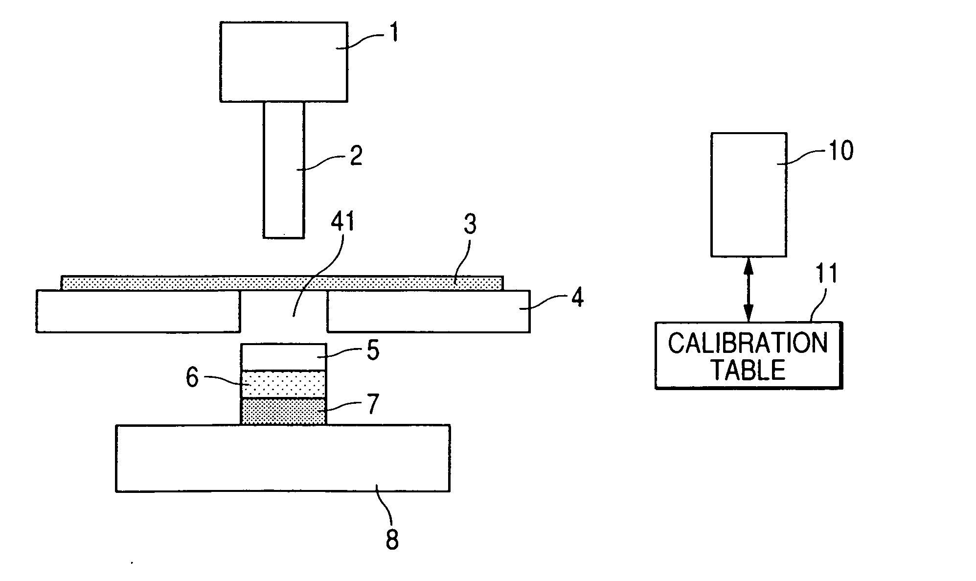
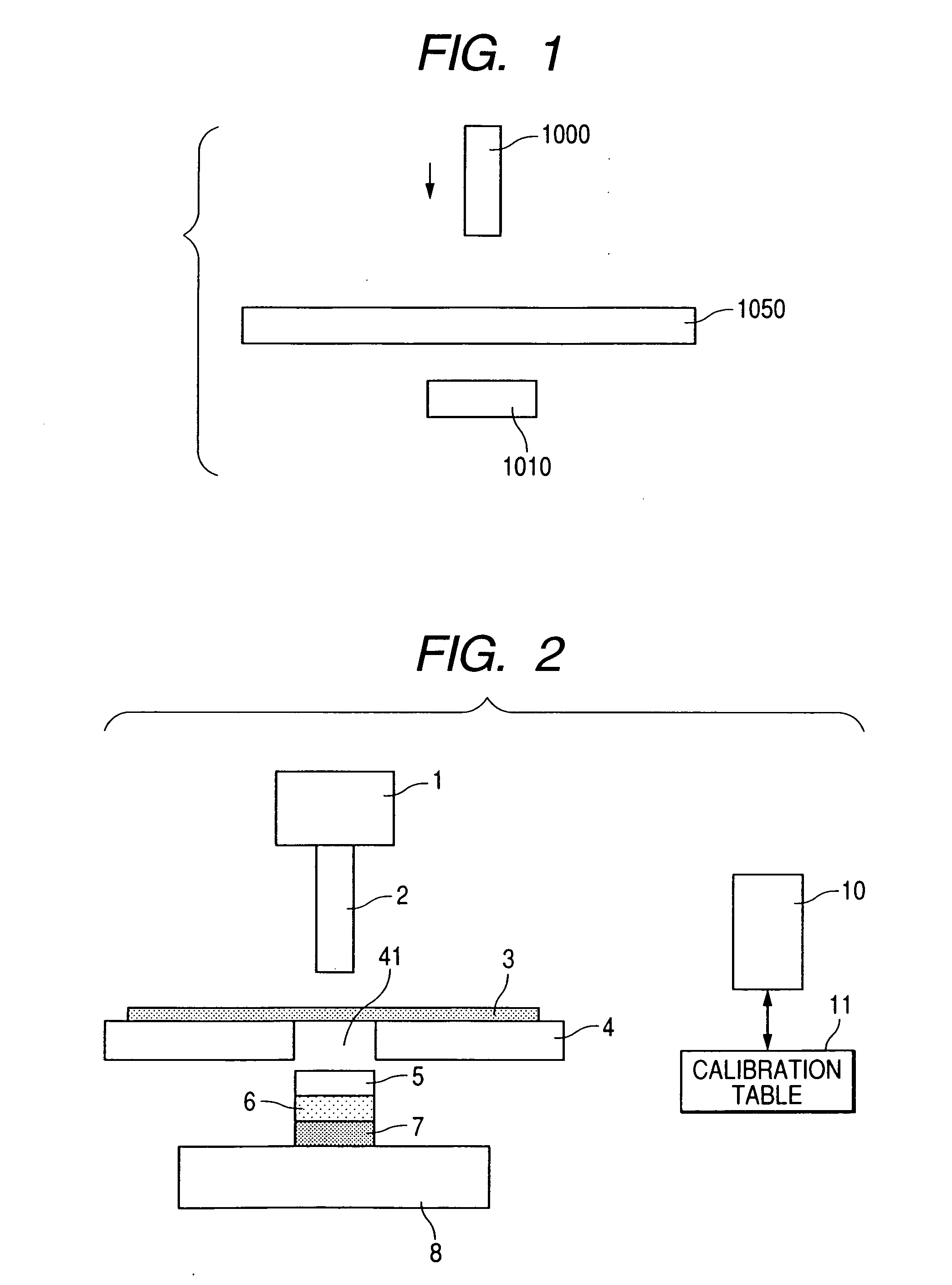
[0088] Moisture was measured with a moisture-measuring device shown in FIG. 2.

[0089] In this Example, force-applying member 2 was a stainless-steel round column of 3.5 mm diameter, having a weight of 4 g adjusted by controlling the length, and having a flat tip end. Measurement table 4 for placing sample sheet 3 was a stainless steel plate of 2 mm thick, having rectangular aperture 41 of 10 mm×30 mm at the center. Force-receiving member 5 was a stainless steel plate of 5 mm×5 mm and 1.5 mm thick. Piezoelectric element 6 had a size of 5 mm×10 mm and 30 μm thick. Damping member 7 was a nitrile rubber of 5 mm×5 mm and 2 mm thick. The force-receiving member 5, piezoelectric element 6, and damping member 7 were bonded by an adhesive together and were placed so as to have a center line common to aperture 41 formed in measurement table 4.

[0090] Pedestal 8 for fixing force-receiving member 5, piezoelectric element 6, and damping member 7 was a stainless steel plate of 7 mm×60 mm and 5 mm ...

example 2

[0099] Moisture was measured with a moisture-measuring device shown in FIG. 8.

[0100] The moisture-measuring device shown in FIG. 8 employed force-applying member 1A shown in FIG. 5 in place of force-applying member 1 shown in FIG. 2. With force-applying member 1A shown in FIG. 5, the external force applied to sample sheet 3 could be detected by piezoelectric element (pressure sensor) 6A provided with force-applying member 2 on force-applying unit 1A on the upper side of sample sheet 3 as well as by piezoelectric element (pressure sensor) 6 placed at the bottom of force-receiving member 5.

[0101] In this Example, the moisture content can be measured by either one of piezoelectric elements 6 and 6A or the both thereof. However, with the upper piezoelectric element 6A, the moisture content is preferably measured by the rebound time rather than the generated voltage. With the lower piezoelectric element 6, the moisture content may be measured by any of the rebound time and the first vo...

example 3

[0119] The moisture-measuring device shown in FIG. 2 is mounted on an image-forming apparatus such as a copying machine, an LBP, and an inkjet printer.

[0120]FIG. 9 illustrates constitution of a portion of an image-forming apparatus having a moisture-measuring device of the present invention and an image-forming assembly not shown in the drawing for forming an image on sheet 3. In FIG. 9, the symbol 4A denotes a sheet delivery table of a sheet delivery system of the image-forming apparatus. Sheet 3 is delivered at a prescribed speed along the upper face of this sheet delivery table 4A. Sheet delivery table 4A has aperture 41,. The shape of the aperture is not limited, and may be circular, ellipsoidal, or corner-rounded pentagonal, provided that the aperture does not interfere with the delivery of sheet 3.

[0121] The numeral 20 denotes rollers for delivering sheet 3. Rollers 20 are not limited at all in the set position, the shape, and the material. In FIG. 9, two pairs of rollers 20...


PUM


Abstract

A moisture data-acquiring device for acquiring data on moisture contained in a sheet comprises a force-applying unit for applying an external force to the sheet, a force-receiving unit for receiving the external force through the sheet, a signal outputting unit for outputting a signal reflecting a mechanical property of the sheet which unit is placed on at least one of the force-applying unit and the force-receiving unit, and a moisture data-acquiring unit for acquiring data on moisture of the sheet based on the signal from the signal outputting unit.

Description

BACKGROUND OF THE INVENTION [0001] 1. Field of the Invention [0002] The present invention relates to a moisture data-acquiring device (a water content information-acquiring apparatus), and an image-forming apparatus. [0003] 2. Description of Related Art [0004] Moisture-measuring devices are known as apparatuses for acquiring information on moisture such as a water content in a sheet material like recording paper sheets and postcards. [0005] An example of the moisture-measuring device is an optical apparatus which determines the moisture content in a sheet material by measuring light absorption or light reflection. [0006] The optical type device isolates light of the absorption wavelength 1.94 μm of water, and light of plural reference wavelengths from continuous spectrum light, for example, by a spectroscope or a wave filter, and measures the water content by comparison of absorbance or reflectivity of the light by water with those of the reference light (e.g., Japanese Patent Appli...

Claims


Application Information

Patent Timeline
IPC IPC(8): G01N3/00G01N3/02G01N3/32G01N19/10G01N33/34G03G15/00
CPCG01N19/10G01N33/346G01N2203/0005G01N2203/0078G01N2203/0282G03G15/5029
Inventor KANEKO, NORIOKAWASAKI, TAKEHIKO
Owner CANON KK
Why Eureka
Try Eureka