Controlled release bioactive agent delivery device

a bioactive agent and controlled release technology, applied in the field of delivery devices, can solve the problem that the device itself does not provide any other significant function, and achieve the effect of reducing the risks and disadvantages of more invasive surgical techniques, and minimizing damage and interference with body tissues

Inactive Publication Date: 2005-12-08
ANDERSON ARON B +5
View PDF99 Cites 133 Cited by
  • Summary
  • Abstract
  • Description
  • Claims
  • Application Information

AI Technical Summary

Benefits of technology

[0013] The present invention provides devices and methods for providing one or more bioactive agents to a treatment site within the body in a controllable manner. The invention can provide particular advantages when used to deliver bioactive agent(s) to limited access regions of the body. Preferred embodiments of the invention relate to devices and methods for providing bioactive agent(s) to treatment sites in a manner that minimizes damage and interference with body tissues and processes. A primary function of the inventive device is to deliver the bioactive agent(s) to a desired treatment site within the body, and in preferred embodiments, the device itself does not provide any other significant function. That is, once the desired treatment of the body has been accomplished, the device is preferably removed from the body. Moreover, preferred embodiments of the invention provide a device that is minimally invasive such that risks and disadvantages associated with more invasive surgical techniques can be reduced.
[0021] In some embodiments, the configuration of the device can be manipulated to control release of the bioactive agent. For example, the surface area and / or size of the device can be manipulated to control dosage of the bioactive agent(s) provided to the implantation site. In preferred embodiments, the geometry and / or surface area of the body member can be manipulated by choice of wire diameter, coil spacing, device length, device diameter, and the like. Preferably, the device provides increased surface area for delivery of bioactive agent, as compared to a substantially linear device having the same length and width. This increased surface area can be desirable when the implantation site will better accommodate a shorter device (for example, in the eye), or a more narrow device.
[0022] Preferably, the configuration of the controlled release device provides one or more mechanical advantages, such as a built-in anchoring mechanism that reduces or prevents unwanted movement of the device within the body, reduced risk of unwanted ejection of the device from the body, and the like. Moreover, preferred embodiments of the invention can provide minimally invasive devices and methods for delivering one or more bioactive agents to a treatment site within the body. Accordingly, the invention can, in some embodiments, reduce risks of infection and complications associated with more invasive surgical procedures, as well as improve recovery time for patients requiring such treatments.
[0023] In preferred embodiments, the inventive device is easily retrievable from the body, such that the device is placed within the body only for the required treatment duration, and is removed upon completion of a treatment course. Preferably, the device provides enhanced durability of the coated composition, and thus the coated composition (minus the released bioactive agent) is removed from the implantation site upon completion of a treatment course. This can avoid potential harmful effects that could arise if one or more components of the device were left within the body beyond the treatment course (for example, if some of the coating is sheared off the device or otherwise delaminates from the body member).
[0024] Surprisingly, preferred embodiments of the invention provide devices and methods of reproducibly releasing bioactive agent in a linear manner over extended periods of time. As described herein, in vitro elution assays of preferred embodiments of the invention show surprisingly controllable release of bioactive agent over time. In preferred embodiments, coating compositions having varying formulations (in terms of polymer ratios) can provide substantially linear release rates of bioactive agent. Based upon the in vitro data presented herein, it is expected that in vivo release rates will provide reproducible release rates in a linear manner over an extended period of time. See Jaffe et al., Safety and Pharmacokinetics of an Intraocular Fluocinolone Acetonide Sustained Delivery Device, Investigative Ophthalmology & Visual Science, 41:3569-3575 (2000). Thus the invention can provide controlled release of bioactive agent to an implantation site that can be adjusted to accommodate desired treatment duration and dosage. Because the invention provides local delivery of one or more bioactive agents to an implantation site, the invention also preferably avoids toxic levels of bioactive agents that can be required during systemic treatment.
[0026] Structural features can also provide preferred durability characteristics to the inventive device. According to the invention, at least a portion of the body member deviates from the direction of extension, thereby providing a device that provides structural durability before, during, and after implantation in the body. The structure of the body member is preferably chosen to effectively translate force applied by an interventionalist during implantation and / or explantation to provide desired advanceability (described herein) and thus withstand forces that can compromise the structural integrity of the device. Moreover, when the surface of the body member includes surface configurations (for example, micro-etched surfaces, roughened surfaces, and the like), adhesion of the polymeric coating composition to the body member surface can be improved.

Problems solved by technology

A primary function of the inventive device is to deliver the bioactive agent(s) to a desired treatment site within the body, and in preferred embodiments, the device itself does not provide any other significant function.

Method used


Image

  • Controlled release bioactive agent delivery device
  • Controlled release bioactive agent delivery device
  • Controlled release bioactive agent delivery device

Examples


example 1

Release of Triamcinolone Acetonide from Stainless Steel Wires

[0167] Three different polymer solutions were prepared in tetrahydrofuran (THF) in the manner provided below in order to provide coating compositions in the form of a one-part system. The three solutions contained varying amounts of poly(ethylene-co-vinyl acetate), with a vinyl acetate content of 33% (w / w), relative to the amount of poly(n-butyl)methacrylate, with an approximate weight average molecular weight of 337 kD. Each of the three solutions contained a constant amount of triamcinolone acetonide relative to the total polymer weight.

[0168] The coating compositions were prepared as follows. The polymers were initially added to the THF and dissolved overnight while mixing on a shaker at 200 revolutions per minute (rpm) at room temperature (approximately 20° C. to 22° C.). After dissolution of the polymer, the triamcinolone acetonide was added, and the mixture was placed back on the shaker at 100 rpm for 1 hour, to fo...

example 2

In Vitro Release of Triamcinolone Acetonide from Helical Coils

[0177] Two different solutions were prepared in tetrahydrofuran (THF) as in Example 1. The compositions prepared are summarized in Table III:

TABLE IIICoating Compositions applied to the Helical Coil.Parts by weightWeight of coatedCoatingComposition(pbw)composition (μg)Coating 1dTA / pEVA / pBMA50 / 27.5 / 22.51950Coating 1eTA / pEVA / pBMA50 / 40 / 101928

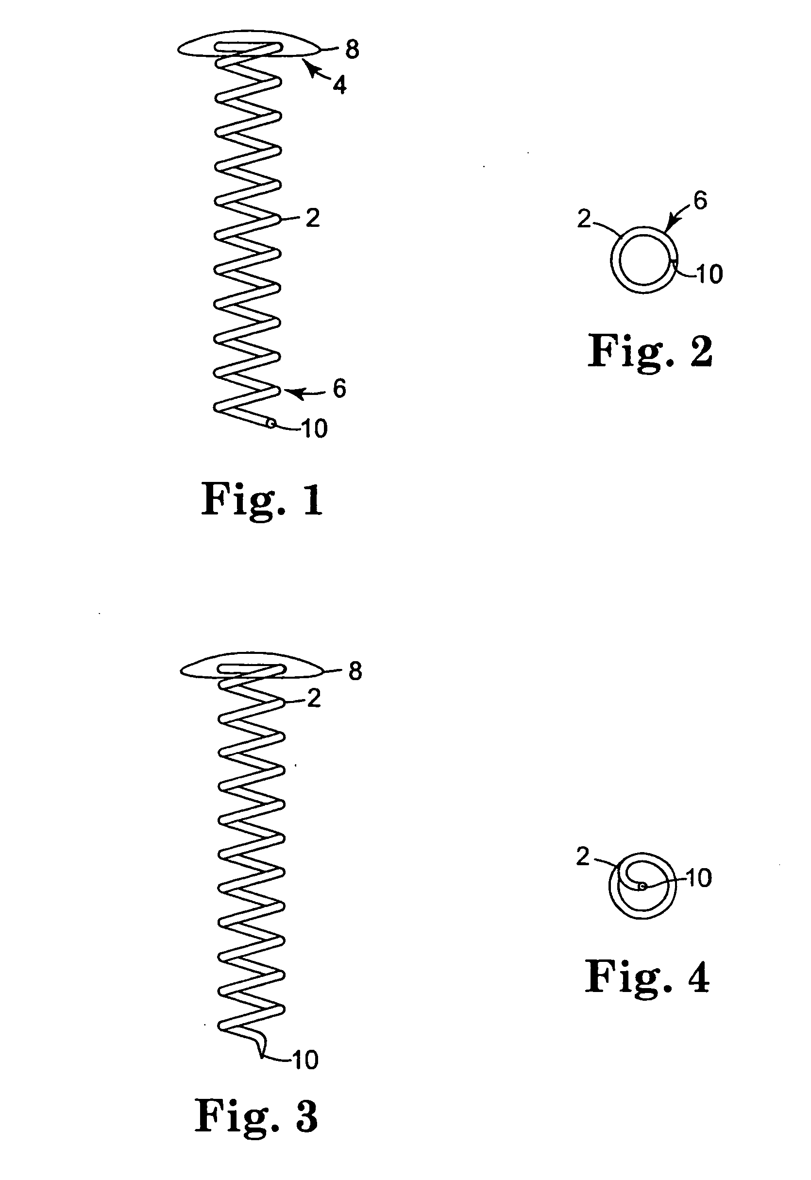
[0178] Helical coils with attached caps were fabricated from the alloy MP35N™ (commercially available from ESPI, Ashland, Oreg.). The coils were cleaned in an alkaline solution, then rinsed with deionized water. The coils underwent additional cleaning using an isopropyl alcohol wash and rinse. The coils were dried and weighed prior to coating.

[0179] Solutions for Coatings 1d and 1e were sprayed onto the coils using ultrasonic coater equipment that consisted of an ultrasonic spray head (Sono-Tek Milton, N.Y.) and syringe pump system for the coating solution. A pin vise was used to hol...

example 3

In Vivo Release of Triamcinolone Acetonide from Helical Coils

[0184] Ten coils were coated with two different formulations, Dose A and Dose B, and were implanted into the vitreous chamber of rabbit eyes to provide sustained release of triamcinolone acetonide. Table V summarizes the coating compositions applied to the coils in this Example. Dose B was designated a “fast release” coating, and this coating composition included a relatively larger ratio of pEVA to PBMA, as compared to the “slow release” Dose A coating composition.

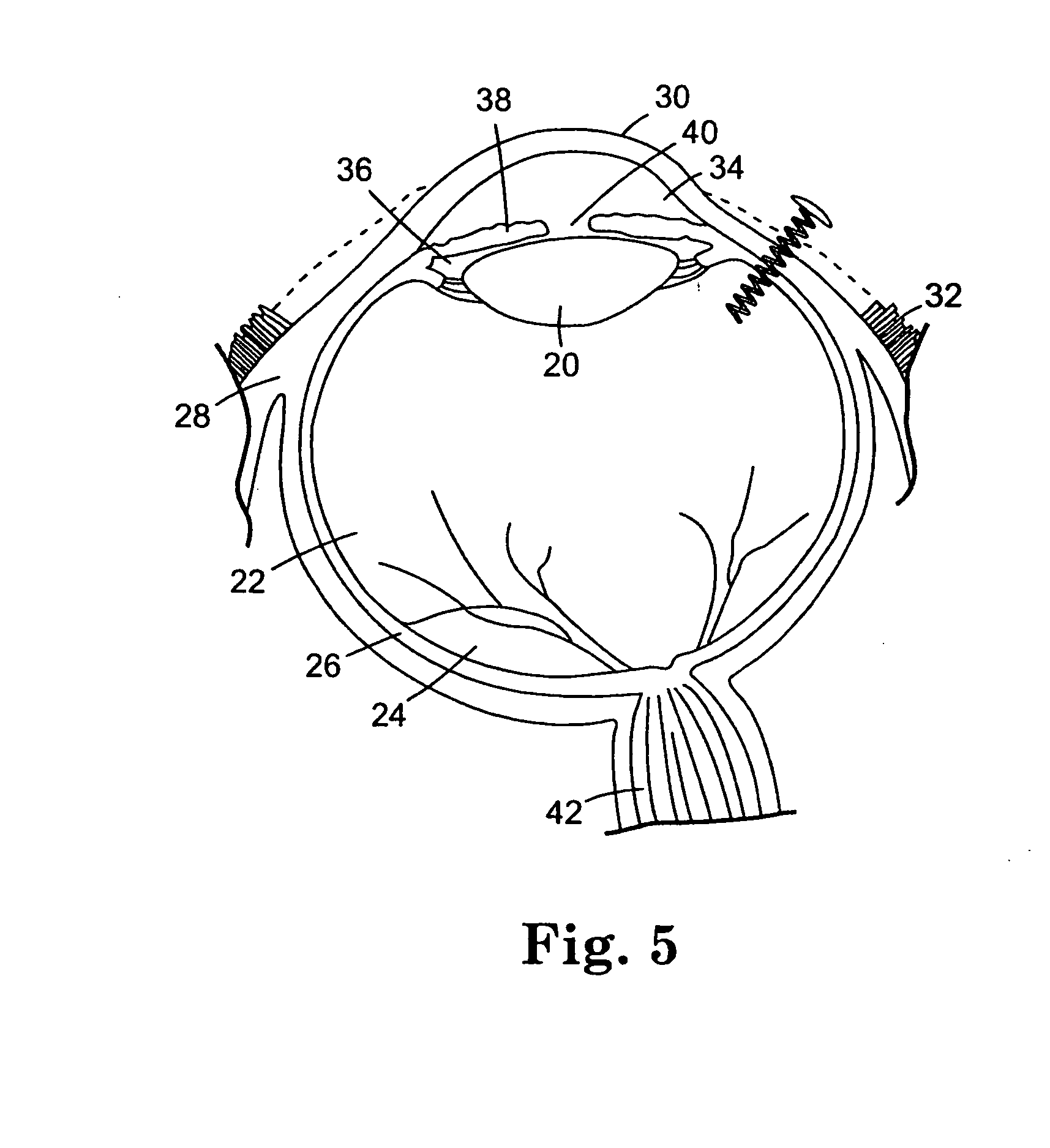
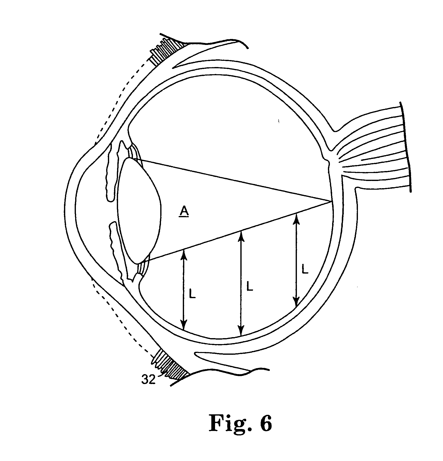
[0185] The coating solutions were prepared according to the procedure described in Example I. The coating solutions were applied to the coils according to the procedure described in Example II. The coated coils were implanted into the vitreous chamber of rabbit eyes as follows. The conjunctiva was dissected and pulled away from the incision site, and an incision was made into the eyes utilizing a needle stick through the sclera. A self-starting coil that inclu...


PUM


Abstract

The invention provides methods for delivering bioactive agent to an eye, the methods including steps of providing a device at an implantation site within the eye, and maintaining the device at the implantation site to provide a therapeutically effective amount of the bioactive agent to the eye. The device includes a body member having a direction of extension, a longitudinal axis along the direction of extension, and a proximal end and a distal end, wherein at least a portion of the body member deviates from the direction of extension. A polymeric coated composition is provided in contact with a surface of the body member, the polymeric coated composition including a first polymer, a second polymer, and a bioactive agent. The invention also provides methods of administering a therapeutically effective amount of bioactive agent to a posterior segment of an eye.

Description

[0001] This application is a continuation of U.S. application Ser. No. 10 / 835,530, filed Apr. 29, 2004, entitled “CONTROLLED RELEASE BIOACTIVE AGENT DELIVERY DEVICE”, which claims the benefit of U.S. Provisional Application Ser. No. 60 / 467,419, filed May 2, 2003, entitled “CONTROLLED RELEASE BIOACTIVE AGENT DELIVERY DEVICE,” which applications are incorporated herein by reference in their entirety.FIELD OF THE INVENTION [0002] The invention relates to a delivery device for controlled delivery of one or more bioactive agents to a treatment site within the body. BACKGROUND OF THE INVENTION [0003] Many surgical interventions involve placement of a medical device into the body. While beneficial for treating a variety of medical conditions, the placement of metal or polymeric devices in the body can give rise to numerous complications. Some of these complications include increased risk of infection, initiation of a foreign body response (which can result in inflammation and / or fibrous en...

Claims


Application Information

Patent Timeline
Patent Type & Authority Applications(United States)
IPC IPC(8): A61K9/00A61K31/58
CPCA61F2310/00353A61K9/0051A61K31/58A61P27/02
Inventor ANDERSON, ARON B.LAWIN, LAURIE R.SHEN, BYRON C.JUAN, EUGENE DEVARNER, SIGNE E.CHAPPA, RALPH A.
Owner ANDERSON ARON B
Why Eureka
Try Eureka