Magnetron sputtering apparatus

a sputtering apparatus and magnetron technology, applied in the field of magnetron sputtering apparatus, can solve the problems of deteriorating usable efficiency of the target b>15/b>, ineffective etc., to achieve the improvement of target usable efficiency and sputtering efficiency. , the effect of high sputtering efficiency

Inactive Publication Date: 2005-12-15
VICTOR CO OF JAPAN LTD
View PDF4 Cites 48 Cited by
  • Summary
  • Abstract
  • Description
  • Claims
  • Application Information

AI Technical Summary

Benefits of technology

[0037] Accordingly, in consideration of the above-mentioned problems of the prior arts, an object of the present invention is to provide a magnetron sputtering apparatus, which enables to uniform erosion of a target as flat as possible while higher sputtering efficiency is realized. The magnetron sputtering apparatus enables to improve usable efficiency of target as well as sputtering efficiency.

Problems solved by technology

Consequently, usable efficiency of the target 15 is deteriorated.
Accordingly, the magnetron sputtering apparatus proposed by the Japanese publication of unexamined utility model applications No. 05-20303 / 1993 is not effective to improve usable efficiency of target.
Accordingly, the third conventional magnetron sputtering apparatus shown in FIG. 35 is not effective to improve usable efficiency of target.

Method used


Image

  • Magnetron sputtering apparatus
  • Magnetron sputtering apparatus
  • Magnetron sputtering apparatus

Examples


first embodiment

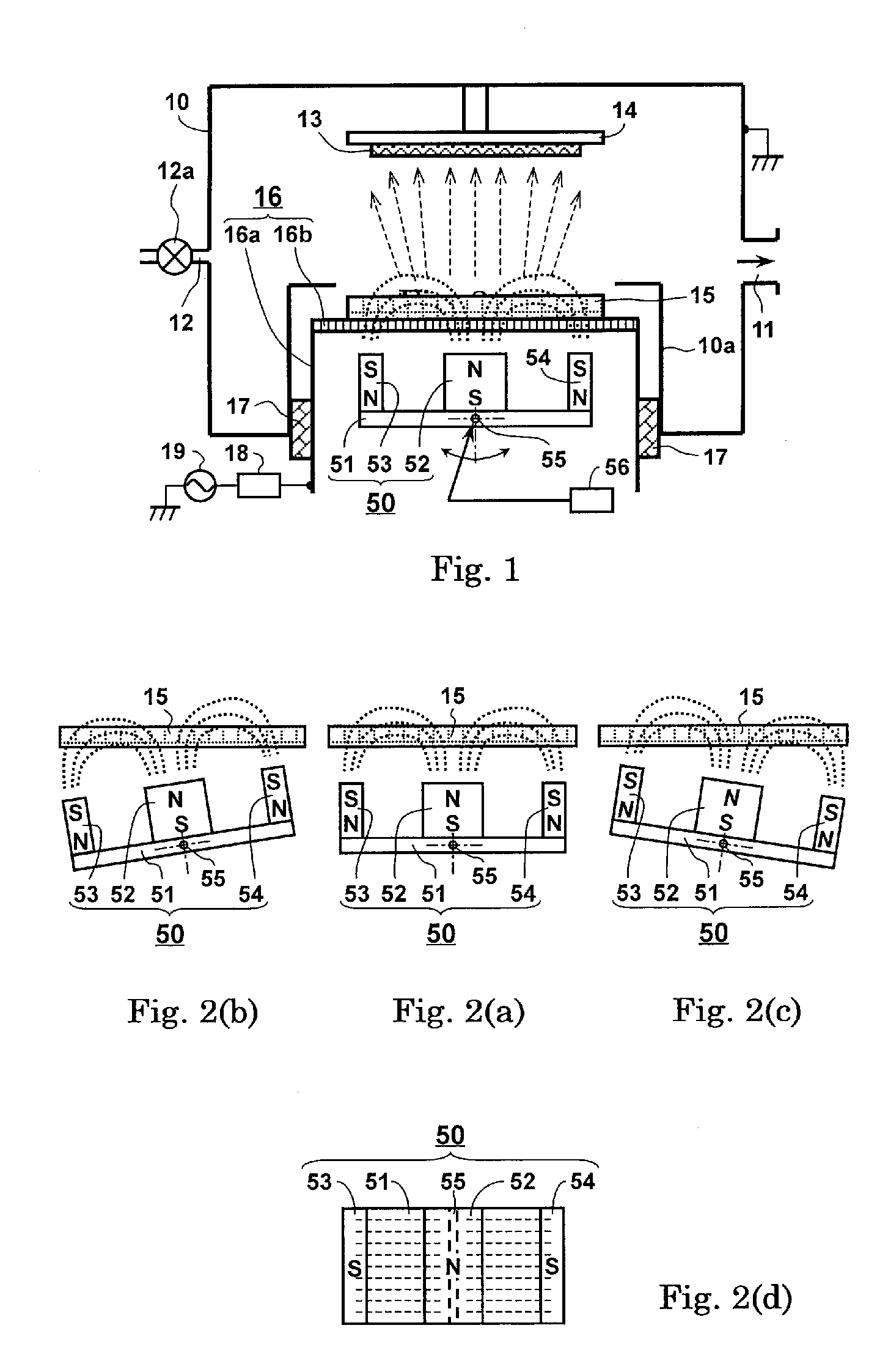
[0082]FIG. 1 is a cross sectional view of a magnetron sputtering apparatus according to a first embodiment of the present invention.

[0083] FIGS. 2(a) to 2(c) are pattern diagrams showing a relationship between a magnetic field (magnetic flux lines) and a target when swinging a magnetic field generating section of the magnetron sputtering apparatus shown in FIG. 1.

[0084]FIG. 2(d) is a plan view of the magnetic field generating section shown in FIGS. 1 and 2(a) to 2(c).

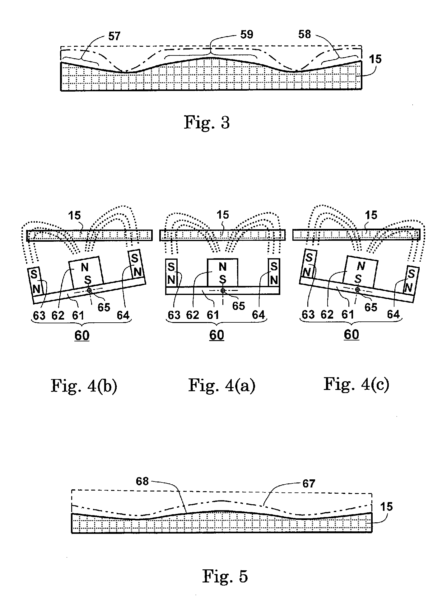
[0085]FIG. 3 shows a cross sectional view of an erosion portion formed on a target when being sputtered by the magnetron sputtering apparatus according to the first embodiment of the present invention.

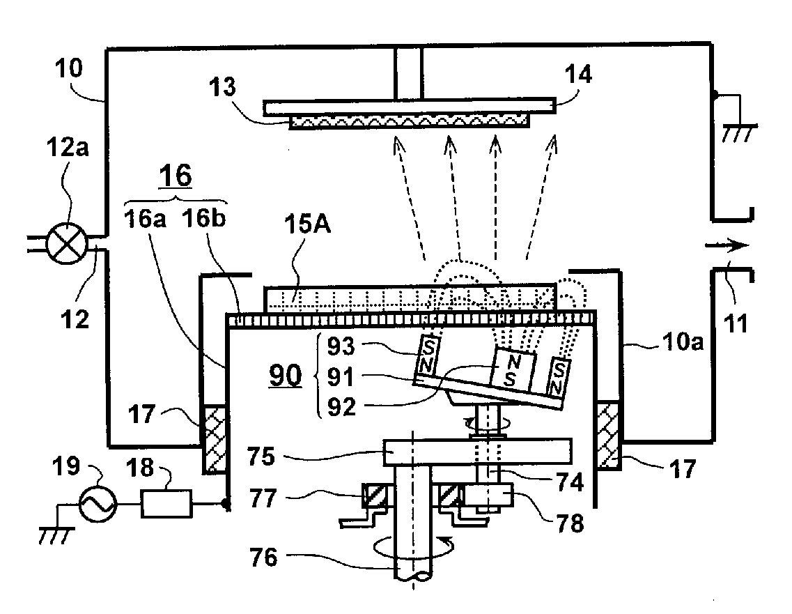
[0086] In FIG. 1, a magnetron sputtering apparatus is composed of a vacuum chamber 10, a substrate 13, an anode 14, a target 15, a cathodic body 16 and a magnetic field generating section 50. The vacuum chamber 10 is provided with an exhaust opening 11, which is connected to a not shown vacuum pump, and a gas intake du...

second embodiment

[0102] A magnetron sputtering apparatus according to a second embodiment is identical to that shown in FIG. 1 according to the first embodiment of the present invention except for the magnetic field generating section 50, so that description is mainly given to operations of a magnetic field generating section.

[0103] FIGS. 4(a) to 4(c) are pattern diagrams showing a relationship between a magnetic field (magnetic flux lines) and a target when swinging a magnetic field generating section of the magnetron sputtering apparatus according to the second embodiment of the present invention.

[0104]FIG. 5 shows a cross sectional view of an erosion portion formed on a target when being sputtered by the magnetron sputtering apparatus according to the second embodiment of the present invention.

[0105] In FIGS. 4(a) to 4(c), a magnetic field generating section 60 is composed of a yoke 61 in flat plate corresponding to the target 15 in square and three permanent magnets 62, 63 and 64 in rectangul...

third embodiment

[0113] A magnetron sputtering apparatus according to a third embodiment is identical to that shown in FIG. 1 according to the first embodiment of the present invention except for the target 15, the magnetic field generating section 50 and the driving unit 56, so that the same components are denoted by the same reference signs and details of their functions and operations are omitted and description is mainly given to operations of a magnetic field generating section.

[0114]FIG. 6 is a cross sectional view of a magnetron sputtering apparatus according to a third embodiment of the present invention.

[0115]FIG. 7 is a plan view of a supporting mechanism and a rotation and revolution mechanism of a magnetic field generating section in the magnetron sputtering apparatus shown in FIG. 6.

[0116]FIG. 8 shows a cross sectional view of an erosion portion formed on a target when being sputtered by the magnetron sputtering apparatus according to the third embodiment of the present invention.

[0...


PUM

PropertyMeasurementUnit
magnetic fieldaaaaaaaaaa
magnetic field strengthaaaaaaaaaa
diameteraaaaaaaaaa

Abstract

A magnetron sputtering apparatus is composed of a vacuum chamber (10), a target (15), a substrate (13), an anode (14) for supporting the substrate (13) that is disposed in the vacuum chamber, a cathodic body (16) for supporting the target (15) that is allocated so as to confront with the anode (14) and a magnetic field generating section (50) for generating a magnetic field on a surface of the target (15) that is allocated in neighborhood of one side of the cathodic body (16) opposite to the target (15). The target (15) is in a shape of square flat plate. The magnetic field generating section (50) is further composed of a yoke (51) in flat plate corresponding to the target (15), a first permanent magnet (52) in rectangular parallelepiped that is disposed in the middle of the yoke (51) and second and third permanent magnets (53, 54) in rectangular parallelepiped that are disposed in both end portions of the yoke (51) respectively. The magnetron sputtering apparatus is further composed of a driving unit (56) for swinging the magnetic field generating section (50) within a prescribed angle with centering a line as an axis of rotation, wherein the line passes through an approximate center (56) of the yoke (51) and is perpendicular to magnetic flux lines of the magnetic field and in parallel with the target (15).

Description

BACKGROUND OF THE INVENTION [0001] 1. Field of the Invention [0002] The present invention relates to a magnetron sputtering apparatus, particularly, relates to a magnetron sputtering apparatus, which enables to expand an erosion area while maintaining higher sputtering efficiency and further enables to improve usable efficiency of target. [0003] 2. Description of the Related Arts [0004] A sputtering apparatus has been utilized for forming various kinds of thin films such as conductive films, dielectric films and semiconductive films. A magnetron sputtering apparatus in particular enables to ensure a higher film forming speed by capturing high density plasma in an area neighboring a target. [0005] Further, a magnetron sputtering apparatus enables to generate stable plasma in a pressure range of a high vacuum. The plasma is low in impurity. [0006] Accordingly, a magnetron sputtering apparatus has been established as the mainstream of sputtering apparatuses in the field of forming a th...

Claims


Application Information

Patent Timeline
Patent Type & Authority Applications(United States)
IPC IPC(8): C23C14/32H01J37/34
CPCH01J37/3408H01J37/3455
Inventor ISEKI, TAKAYUKI
Owner VICTOR CO OF JAPAN LTD
Why Eureka
Try Eureka