
Planar broadband inverted F-type antenna and information terminal

a technology of information terminals and inverted f-type antennas, which is applied in the structure of elongated active elements, resonant antennas, radiating elements, etc., can solve the problem that conventional antennas cannot provide the sufficient bandwidth for the 5.0 ghz band, and achieve the effect of stable characteristics

Inactive Publication Date: 2005-12-15
IIDA +1
View PDF1 Cites 10 Cited by
  • Summary
  • Abstract
  • Description
  • Claims
  • Application Information

AI Technical Summary

Benefits of technology

[0008] Therefore, it is an object of the present invention to provide the small, thin, and lightweight planar broadband inverted F-type antenna. It is another object of the present invention to provide the planar broadband inverted F-type antenna realized by means of etching the FPC. It is a further object of the present invention to provide the planar broadband inverted F-type antenna adaptable to the bandwidth specified in the IEEE standard. It is a further object of the present invention to provide the planar broadband inverted F-type antenna enabled to obtain the stable characteristics in the mass-production process.
[0021] The present invention could provide the small, thin, and lightweight planar broadband inverted F-type antenna. Moreover the present invention could provide the planar broadband inverted F-type antenna realized by means of etching the FPC. Still moreover the present invention could provide the planar broadband inverted F-type antenna adaptable to the bandwidth specified in the IEEE standard. The present invention could provide the planar broadband inverted F-type antenna to be able to obtain the stable characteristics in the mass-production.

Problems solved by technology

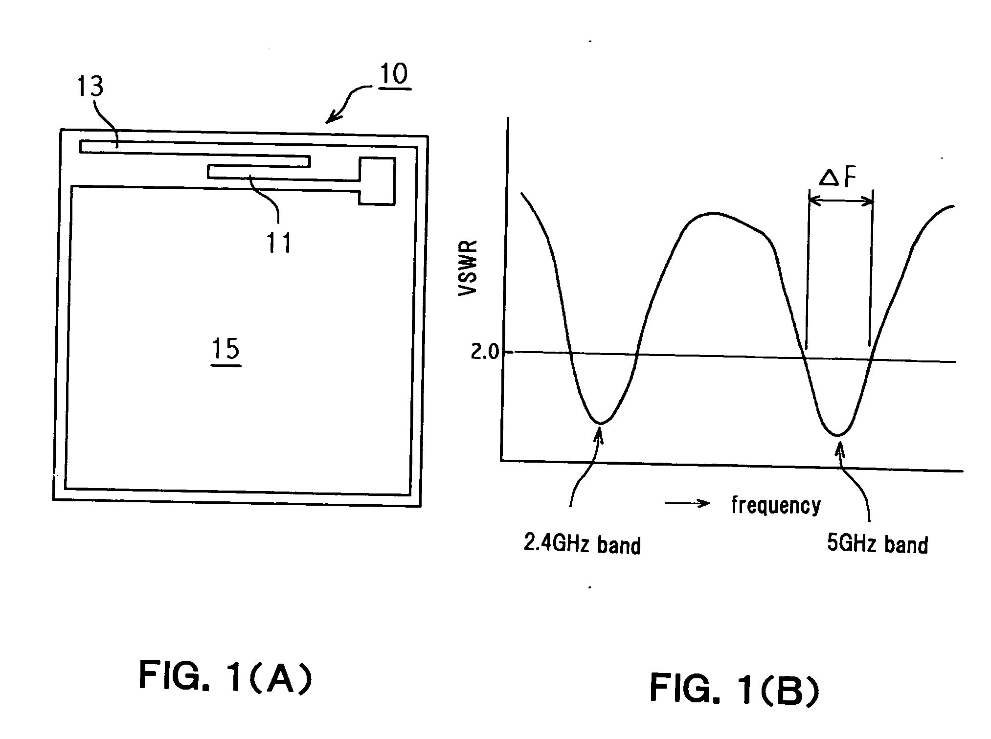
However the conventional antenna could not provide the sufficient bandwidth for the 5.0 GHz band especially.

Method used


Image

  • Planar broadband inverted F-type antenna and information terminal
  • Planar broadband inverted F-type antenna and information terminal
  • Planar broadband inverted F-type antenna and information terminal

Examples


Embodiment Construction

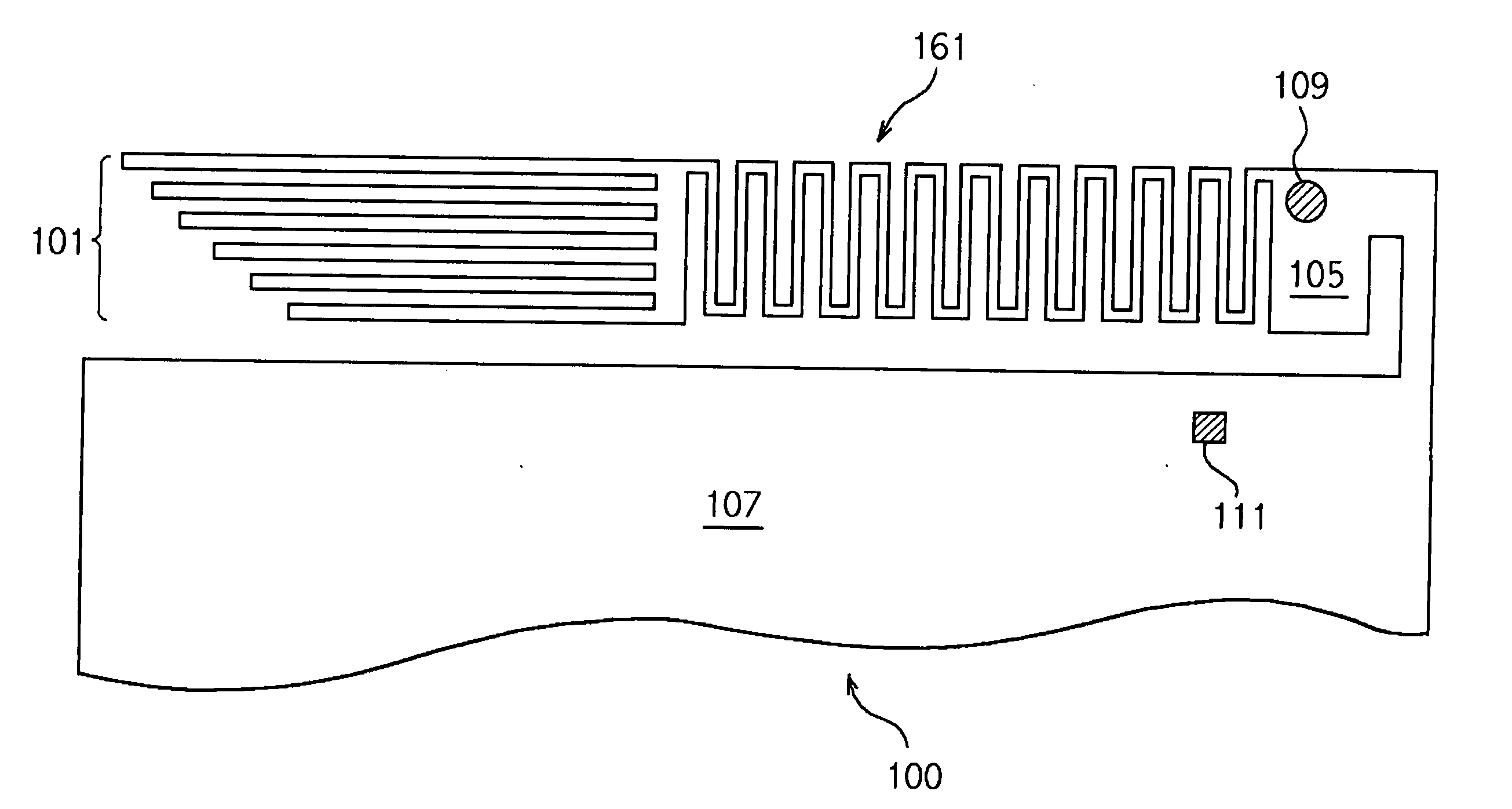
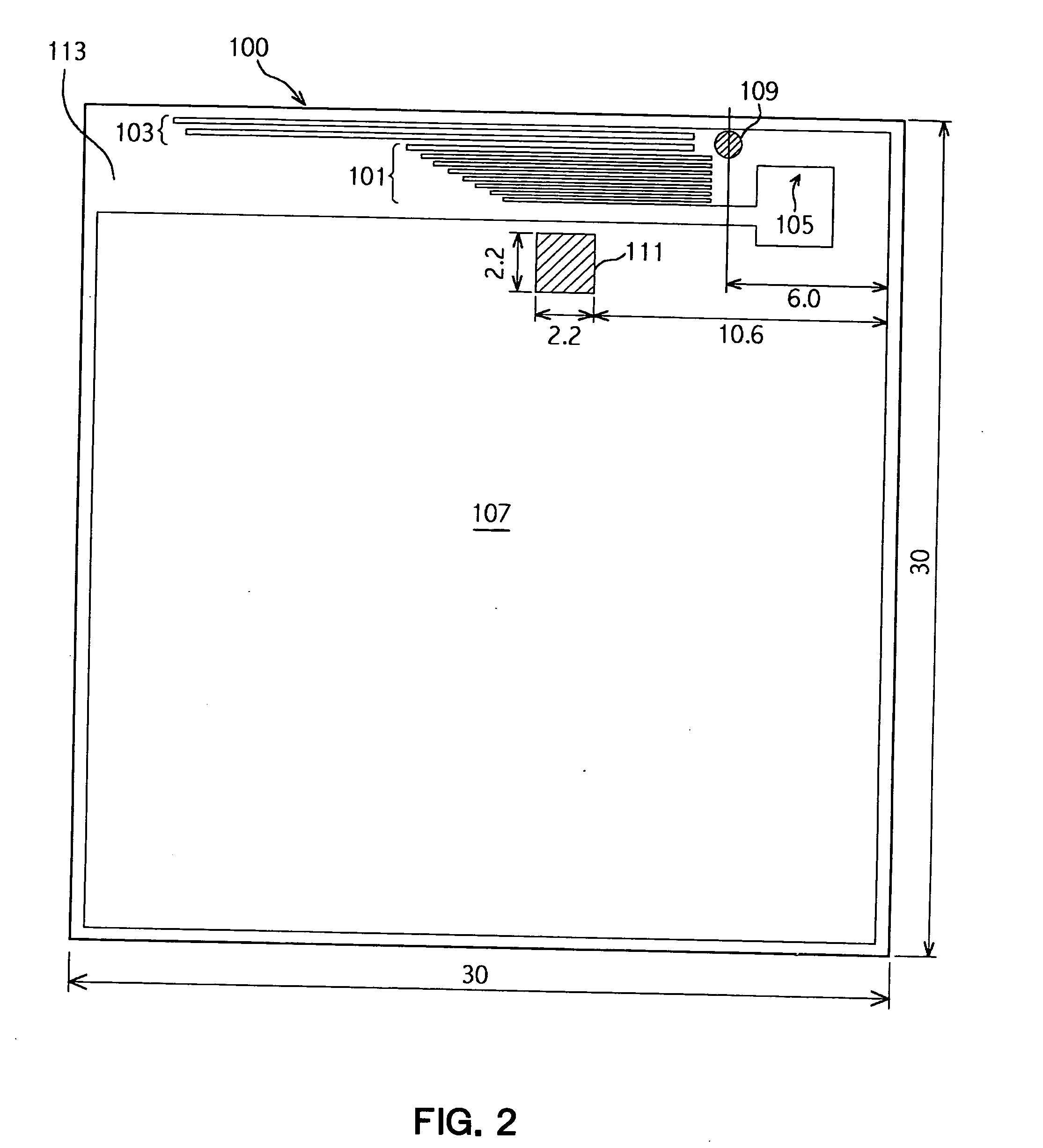
[0046]FIG. 2 is a plane view illustrating the planar broadband inverted F-type antenna (referred as antenna hereafter) according to an embodiment of the present invention. FIG. 3 is an enlarged view of emission patterns of the 5.0 GHz element 101 and emission patterns of the 2.4 GHz element 103. An identical reference number is assigned to an identical element through the specifications entirely. The antenna 100 is manufactured by applying an etching (lithography) technology to a copper foil layer of a commercial FPC corresponding to the conductive layer, where the copper foil layer is laminated on one side or both sides of a polyethylene terephthalate (PET) film 113 corresponding to the base film. A polyimide film can be used as a base film of the FPC.

[0047] A method for manufacturing the antenna by means of etching the FPC will be explained in detail later. The cover film is provided on the copper foil layer to be protected from oxidization or adherent of solder splash generated ...


PUM


Abstract

A planar broadband inverted F-type antenna has a pattern formed by etching a conductive foil laminated on the obverse side and the reverse side of the PET film 113. The antenna is applicable to the 5.0 GHz frequency band. The ground 107, the antenna element 101, and the connection element 105 are formed on the obverse side. The ground has the ground point connectable to the ground line of the feeding wire. The antenna element has a plurality of emission patterns adaptable to the 5.0 GHz frequency band. Each pattern has the length varying from each other. The connection element connects each emission pattern to the ground. The feeding pattern 183, which is formed on the reverse side, has the feeding terminal 181 connectable to the voltage line of the feeding wire. The feeding pattern is connected to the connection element. The feeding pattern includes a parallel wiring component to the emission patterns. The feeding pattern is positioned to overlap the vertical projection with at least one of the emission patterns so that the phase adjustment is provided to decrease the voltage standing wave ratio.

Description

FIELD OF THE INVENTION [0001] The present invention relates to a planar broadband inverted F-type antenna suitable to a broad bandwidth, and more particularly relates to the planar broadband inverted F-type antenna manufactured by etching an flexible printed circuit (FPC) and suitable to the broad bandwidth. BACKGROUND OF THE INVENTION [0002] Installation of a wireless LAN system in a mobile information terminal such as a notebook type personal computer or PDA (Personal Digital Assistant) is increasing in accordance with development of lightweight structure and miniaturization. A standard for two frequency bands of the wireless LAN system is now established for a 2.4 GHz band (IEEE802.11b / g) and a 5.0 GHz band (IEEE802.11a) under a working group of IEEE (the Institute of Electrical and Electronic Engineers). Accordingly, the antenna capable of being used in these two frequency bands is required from the information terminal equipped with the wireless LAN system. A planate antenna or...

Claims


Application Information

Patent Timeline
IPC IPC(8): H01Q1/22H01Q1/24H01Q1/38H01Q5/00H01Q5/10H01Q5/371H01Q9/04H01Q9/30
CPCH01Q1/2258H01Q1/243H01Q5/371H01Q9/0421H01Q9/0442H01Q1/38
Inventor ENDO, SHUICHITANIGUCHI, KANAZUAIDA, KATSUHISANEMA, KEN
Owner IIDA
Learn More