
Apparatus and method for inspecting golf balls using infrared radiation

Inactive Publication Date: 2005-12-15
ACUSHNET CO
View PDF12 Cites 21 Cited by
  • Summary
  • Abstract
  • Description
  • Claims
  • Application Information

AI Technical Summary

Benefits of technology

[0014] The image of step (ii) comprises an array of pixels, and each pixel is represented by a numerical value indicative of a color or brightness of each pixel. In one embodiment, if the sum of the numerical values of the pixel is different from a total threshold value by more (or less) than a predetermined amount then the liquid was applied unevenly. The total threshold value can be ascertained from a calibrated object, wherein said calibrated object has the liquid evenly app

Problems solved by technology

Moreover, if a major defect, such as a gross cosmetic defect or a defect affecting performance or durability, is found, the manufacturer may choose to shut down the entire system.
On the other hand, automation of the manufacturing process can cause various manufacturing defects.
For example, automated pad-printing equipment may leave smudges from excess ink carried by the printing pad.
Vibration or improper set-up, such as improper positioning or accidental switching of the paint supply hoses cutting off paint supply to the spray guns, causes defective coating on golf balls.
Moreover, the clear coat paint may periodically clog the spray booth filter, interfering with proper spraying of paint.
While clear coat spray painting operation utilizing catalyzation can significantly reduce the curing time, catalyzation can also occur in the spray booth, resulting in a thick brittle coating on the spray booth filter and increasing the probability of spray paint malfunctions.
Clogging of spray guns and gelling of the clear coat during application result in inadequate clear coating of the golf ball.
Moreover, transferring the freshly coated golf ball to the curing station before inspection does not alert the operator to attend to unacceptable spray painting apparatus conditions until the end of the curing process.
Another drawback of this system is that at least a portion of the exterior surface of the products to be inspected must be raised about 5° C. to 15° C. higher.

Method used


Image

  • Apparatus and method for inspecting golf balls using infrared radiation
  • Apparatus and method for inspecting golf balls using infrared radiation

Examples


Embodiment Construction

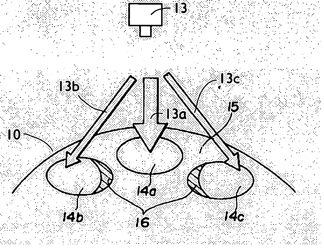
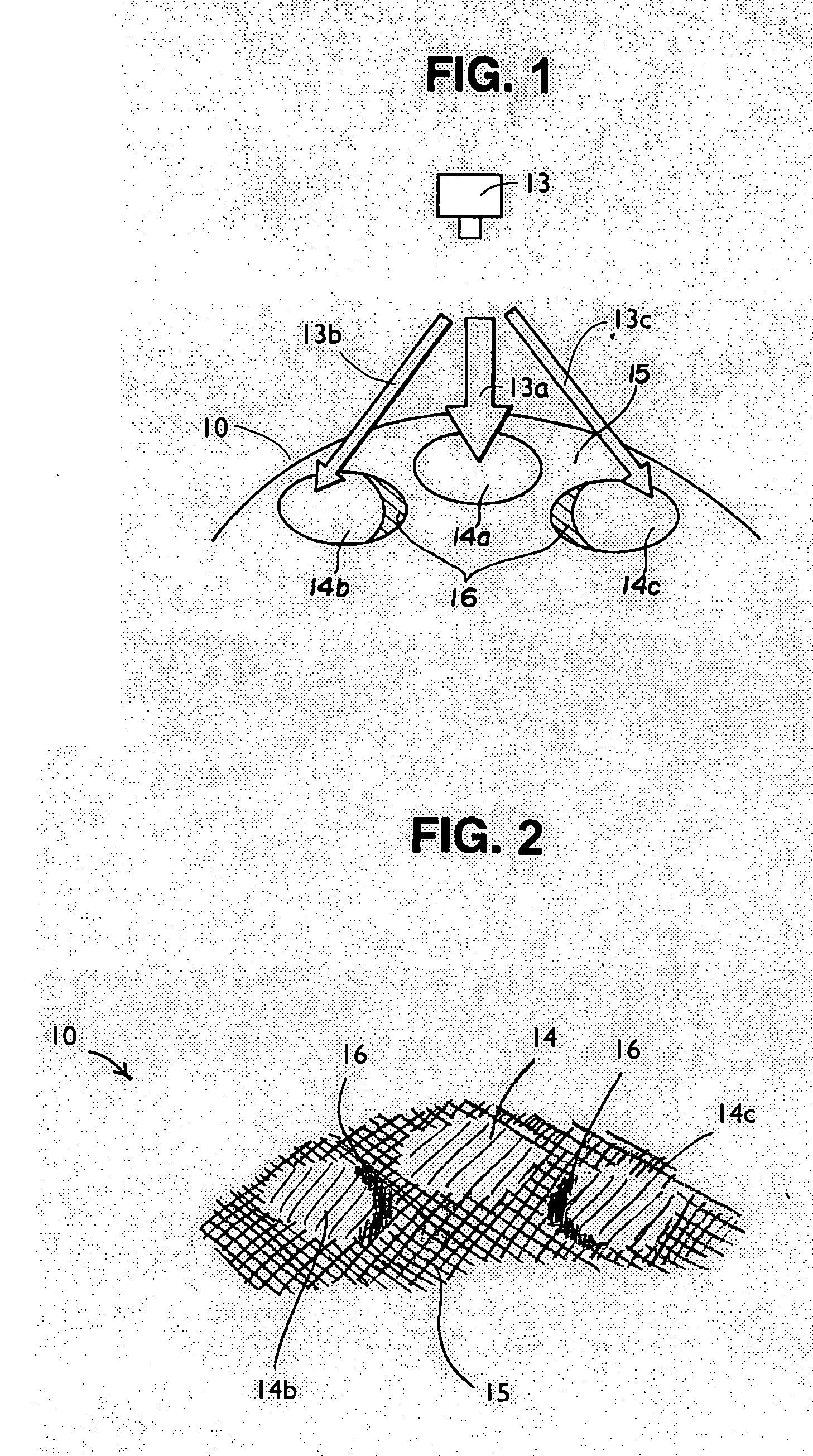
[0019] As shown in FIG. 1, golf ball 10 comprises a plurality of dimples 14a, 14b, 14c et cetera defined on land surface 15. As discussed above, the spray is deposited directly on the surface of the ball. Depending on the relative location between the spray nozzle and the dimples, the spray can completely cover the dimple as illustrated schematically by arrow 13a and dimple 14a when the spray nozzle is located directly above the dimple. When the dimples are offset from the spray nozzle, areas 16 of the dimple may not be covered by the paint or coating, or may not be covered with a desired thickness of paint or coating, as illustrated schematically by arrows 13b, 13c and dimples 14b, 14c leaving areas 16 uncovered or thinly covered.

[0020] In other situations, land area 15 may be thinly covered while the paint or coating may pool inside the dimple. Additionally, the spray nozzle may become partially clogged causing the spray to be asymmetric and create unpainted areas. Hence, it is d...


PUM

PropertyMeasurementUnit
Lengthaaaaaaaaaa
Lengthaaaaaaaaaa
Lengthaaaaaaaaaa

Abstract

A method for inspecting golf balls is disclosed. The method comprises the steps of providing at least one sensor capable of obtaining images of the infrared radiation emitted from the ball, obtaining at least one image of the ball using the sensor after paint or a coating has been applied to the surface of the ball, and determining whether the liquid was applied evenly on the surface of the ball. Preferably, the image is obtained during the transient period when the solvent in the paint or coating is evaporating. A number of numerical analysis can be used to determine the evenness of the paint or coating.

Description

FIELD OF THE INVENTION [0001] This invention generally relates to inspecting golf balls and more specifically to inspecting golf balls using infrared detector systems. BACKGROUND OF THE INVENTION [0002] The manufacture of golf balls typically involves a series of sequential processes performed at different processing stations, typically spatially separated one from another. Golf balls typically have at least a core and a dimpled cover formed over the core. The outer cover of the golf ball is formed with various materials that may be urethane elastomers, balata, ionomers or any other appropriate materials. The cover surfaces are formed with dimples of various numbers, sizes and patterns, which improve flight distance, control and stability. The golf ball cover generally contains a white or other colored concentrate, or is painted. The outer surface of the ball covers usually have the manufacturers indicia disposed thereon as well as an application of a paint or clear coat for the pur...

Claims


Application Information

Patent Timeline
IPC IPC(8): A63B59/00B05D1/00G01N21/84G01N21/95G01N33/00
CPCA63B59/0074G01N21/8422G01N2033/008G01N2021/8427G01N21/951G01N33/008A63B60/42
Inventor HARRIS, KEVIN M.BRUM, WILLIAMST. AUBIN, BRIAN P.MYDLACK, THOMAS L.FURZE, PAUL A.
Owner ACUSHNET CO
Features
  • Generate Ideas
  • Intellectual Property
  • Life Sciences
  • Materials
  • Tech Scout
  • Unparalleled Data Quality
  • Higher Quality Content
  • 60% Fewer Hallucinations
Learn More