Fuel cell separator and a method for manufacturing the same

a technology of fuel cell separator and separator body, which is applied in the direction of cell components, final product manufacturing, sustainable manufacturing/processing, etc., can solve the problems of inability to perform injection molding of resin, limitation of the electrical resistance reduction of the separator, and inability to obtain uniform electrical resistance over the entire outer layer. , to achieve the effect of low electrical resistance and low cos

Inactive Publication Date: 2005-12-15
MITSUBISHI ELECTRIC CORP
View PDF4 Cites 16 Cited by
  • Summary
  • Abstract
  • Description
  • Claims
  • Application Information

AI Technical Summary

Benefits of technology

[0013] Accordingly, the present invention is intended to obviate the problems as referred to above, and has for a first object to obtain a fuel cell separator and a manufacturing method therefor in which the separator of a low electrical resistance can be produced at low cost by placing in a mold a resin block made of a first resin having a high content of electrically conductive particles, and injection molding a second resin containing electrically conductive particles into the mold after the mold has been heated to a temperature equal to or higher than the melting temperature of the first resin.
[0014] Another object of the present invention is to obtain a method for manufacturing a fuel cell separator which is inexpensive and has a low electrical resistance by injection molding a resin containing electrically conductive particles into a mold after electrically conductive particles have been coated on the inner wall surface of the mold.
[0016] According to the present invention, the resin block comprising the first resin is placed in the cavity. As a result, the content of the electrically conductive particles of the first resin can be increased, and hence it is possible to produce a separator with its outer layer part of a low electrical resistance. In addition, the flow length of the first resin becomes short, so the orientation of electrically conductive particles in the skin layer can be reduced. This also serves to provide a separator that has its outer layer part of a low electrical resistance. Moreover, since only the second resin is injection molded, only the flowability of the second resin can be reduced to an injectionable flowability level in consideration of a pressure loss in the gate. Consequently, it is possible to produce a separator that has its core layer part of an accordingly lowered electric resistance.

Problems solved by technology

Accordingly, if the carbon content of resin is increased so as to reduce the electrical resistance of the skin layer, the melt viscosity of the resin becomes large, so it becomes impossible to perform injection molding of the resin.
Thus, in the known separator manufacturing methods, there has been a limitation to the reduction in the electrical resistance of the separator.
Moreover, the formation of such a skin layer precludes a uniform distribution of carbon particles over an area extending from a gate portion at which injection of resins is started up to the flow front of the resins, so it becomes impossible to obtain uniform electrical resistance over the entire outer layer part.
Since the two kinds of resins are injection molded with the single mold, an injection molding machine having two injection devices for these resins, respectively, is required, thus resulting in high production costs.

Method used


Image

  • Fuel cell separator and a method for manufacturing the same
  • Fuel cell separator and a method for manufacturing the same
  • Fuel cell separator and a method for manufacturing the same

Examples


embodiment 1

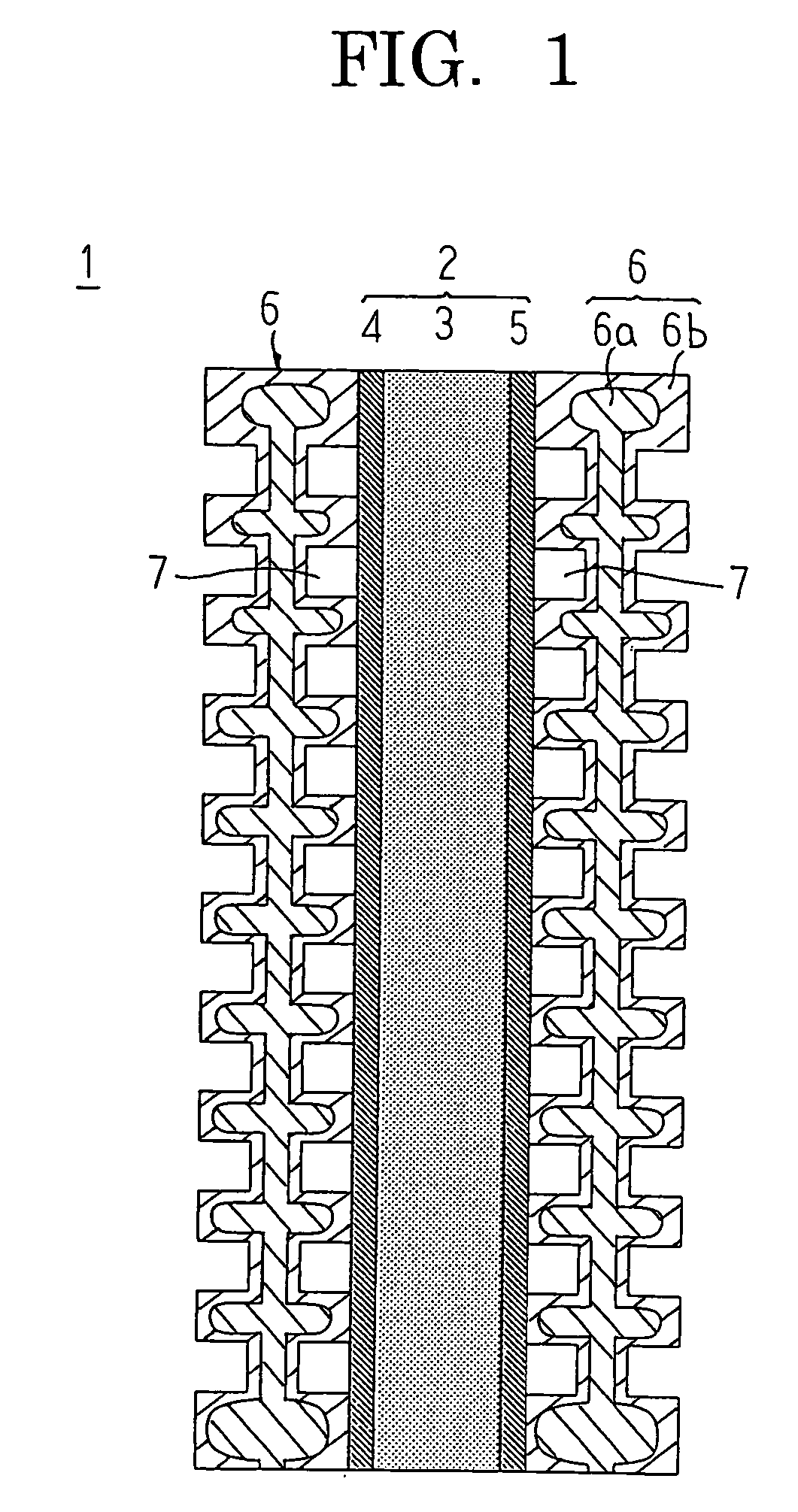
[0025]FIG. 1 is a cross sectional view that schematically illustrates a single cell constituting a solid polymer type fuel cell according to a first embodiment of the present invention.

[0026] In FIG. 1, the single cell, generally designated at reference numeral 1, includes a combined electrode and membrane member 2, and a pair of separators 6 arranged so as to clamp or sandwich the combined electrode and membrane member 2 from its opposite sides.

[0027] The combined electrode and membrane member 2 includes a pair of porous electrodes 4, 5 and an electrolyte membrane 3, and is arranged in such a manner that the porous electrodes 4, 5 each of a rectangular and planar configuration respectively face the opposite sides of the electrolyte membrane 3 of a similarly rectangular and planar configuration so as to be integrally combined therewith. The porous electrodes 4, 5 are formed of a porous medium such as carbon paper, carbon cloth, etc., and are each formed into a rectangular shape of...

example 1

[0055] In this first example, polyphenylene sulfide resin was used as a base resin, and carbon particles were used as electrically conductive particles. Carbon particles were added to the polyphenylene sulfide resin at 70 wt % so that a first resin was prepared and adjusted so as to have a melt shear viscosity of 2×10⁶ Pa.sec at a resin temperature of 290° C. at a shear rate of 1,000 sec−1. In addition, carbon particles were added to the polyphenylene sulfide resin at 65 wt % so that a second resin was prepared and adjusted so as to have a melt shear viscosity of 5×10³ Pa.sec at a resin temperature of 290° C. at a shear rate of 1,000 sec−1.

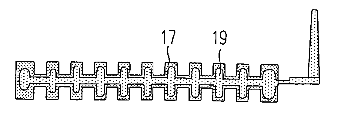
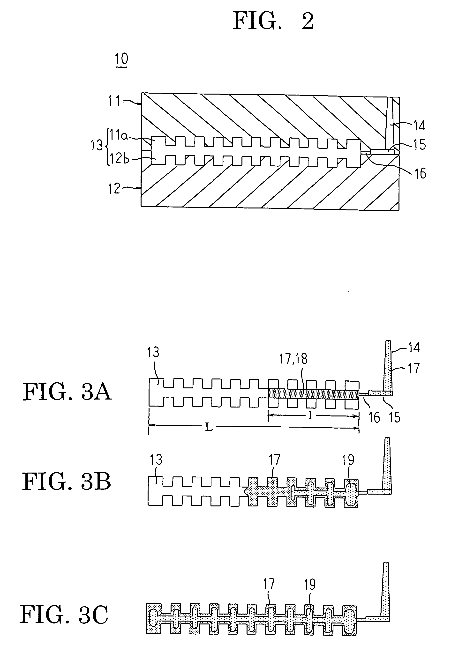
[0056] Subsequently, the first resin thus prepared was press molded to provide a resin block. The resin block was constructed to be of a rectangular and planar configuration having substantially the same thickness as the minimum thickness or distance of a space or cavity in a mold (i.e., thickness between opposed bottoms of gas passages in a sepa...

example 2

[0061] In this second example, polyphenylene sulfide resin was used as a base resin, and carbon particles were used as electrically conductive particles. Carbon particles were added to the polyphenylene sulfide resin at 60 wt % so that a first resin was prepared and adjusted so as to have a melt shear viscosity of 5×10³ Pa.sec at a resin temperature of 290° C. at a shear rate of 1,000 sec−1. In addition, carbon particles were added to the polyphenylene sulfide resin at 50 wt % so that a second resin was prepared and adjusted so as to have a melt shear viscosity of 3×10² Pa.sec at a resin temperature of 290° C. at a shear rate of 1,000 sec−1.

[0062] Subsequently, the first resin thus prepared was press molded to provide a resin block. The resin block was constructed to be of a rectangular and planar configuration having substantially the same thickness as the minimum thickness or distance of a space or cavity in a mold (i.e., thickness between opposed bottoms of gas passages in a sep...


PUM

PropertyMeasurementUnit
melt shear viscosityaaaaaaaaaa

Abstract

A first resin is prepared which has a content of electrically conductive particles adjusted in the range from 60 wt % to 90 wt %, and a melt shear viscosity adjusted in the range from 1×10³ Pa.sec to 1×10⁷ Pa.sec. A second resin is prepared which has a content of electrically conductive particles that is adjusted in the range from 50 wt % to less than 90 wt % and that is less than that of the first resin. The second resin has a melt shear viscosity adjusted in the range from 1×10² Pa.sec to less than 1×10⁵ Pa.sec. A resin block prepared from the first resin is placed in a mold, and the second resin is injection molded into the mold while heating the mold to the melting temperature of the first resin or above.

Description

BACKGROUND OF THE INVENTION [0001] 1. Field of the Invention [0002] The present invention relates to a fuel cell separator and a method for manufacturing the same, and more particularly, to such a fuel cell separator which is injection molded from a resin containing electrically conductive particles as well as to a manufacturing method therefor. [0003] 2. Description of the Related Art [0004] A known fuel cell separator is constructed of a core layer part formed of a resin with a low carbon content and an outer layer part formed so as to cover an outer surface of the core layer part with a resin of a high carbon content (for example, see a first patent document: Japanese patent application laid-open No. 2000-323150). In the known separator as constructed in this manner, a high electrical conductivity is ensured in the outer layer part of a high carbon content, whereas physical strength is obtained in the core layer part of a low carbon content. [0005] Two methods for manufacturing a...

Claims


Application Information

Patent Timeline
Patent Type & Authority Applications(United States)
IPC IPC(8): B29B13/00H01M8/02H01M8/10
CPCH01M8/0213H01M8/0221Y02E60/50H01M8/0228H01M2008/1095H01M8/0226Y02P70/50
Inventor MUKUDA, MUNEAKIINUZUKA, TAKAYUKIMINEGISHI, AKINARI
Owner MITSUBISHI ELECTRIC CORP
Why Eureka
Try Eureka