
Method for controlling an intensity of an infrared source used to detect objects adjacent to an interactive display surface

a technology of infrared light source and display surface, which is applied in the field of controlling the intensity of light, can solve the problems of substantially precluding the accurate detection of objects placed on display surfaces, affecting the ability of ir vision detection system and its ability, and failing to discuss the effect of ambient ir light on sensing ir light reflected from objects

Inactive Publication Date: 2005-12-15
MICROSOFT TECH LICENSING LLC
View PDF82 Cites 56 Cited by
  • Summary
  • Abstract
  • Description
  • Claims
  • Application Information

AI Technical Summary

Benefits of technology

[0006] The present invention is thus intended to control the light emitted by the IR light sources that illuminate the undersurface of an interactive display surface, so that the level of that IR light is greater than the level of the ambient IR light that is passing through the interactive display surface. By thus controlling the IR light sources, the level of IR light emitted thereby is kept at a level sufficient to enable objects placed adjacent to the interactive displays surface to be detected, but avoids emitting a greater intensity IR light than is necessary, which might interfere with other types of IR light responsive devices.
[0008] As noted above, an initial application of the present invention will be used for an interactive display device. Accordingly, for this application, the light source produces IR light, the image that is captured is an IR image, and the ambient light level is an ambient IR light level. Similarly, the diffusing surface comprises an interactive display surface on which an object is detected in response to IR light reflected from the object when the object is disposed adjacent to the interactive display surface. By controlling the intensity of the light source, the IR light reflected from the object will more readily be apparent in the image, relative to the ambient IR light that passes through the interactive display surface.
[0010] It may also be preferable to determine the light level reflected from a plurality of regions that are spaced apart around the diffusing surface instead of from a single region, by capturing all of these regions in the image. If so, the intensity of the light source can be controlled so that the level of the light reflected from all of the plurality of regions exceeds the ambient light level by a predefined amount.

Problems solved by technology

Again, these papers fail to discuss the effects on ambient IR light on sensing IR light reflected from objects to detect the object and do not mention any approach for controlling the intensity of the IR light used for sensing objects in response to the ambient IR light level.
If the ambient IR light source has a greater intensity when sensed to detect an object, it will substantially preclude the accurate detection of an object placed on a display surface.
A bright ambient IR light source will effective wash out the reflection from an object placed on an interactive display surface and will thus interfere with the IR vision detection system and its ability to sense the location of an object on the display surface and other distinctive information that is conveyed by the reflected IR light from an intended IR source that is disposed on an opposite side of the display surface from the IR ambient light source.
However, there may be undesired consequences to this action, since too high an IR light level produced by the intended IR source can adversely affect the operation of other devices that use IR light, such as remote controls.

Method used


Image

  • Method for controlling an intensity of an infrared source used to detect objects adjacent to an interactive display surface
  • Method for controlling an intensity of an infrared source used to detect objects adjacent to an interactive display surface
  • Method for controlling an intensity of an infrared source used to detect objects adjacent to an interactive display surface

Examples


Embodiment Construction

Exemplary Computing System for Implementing Present Invention

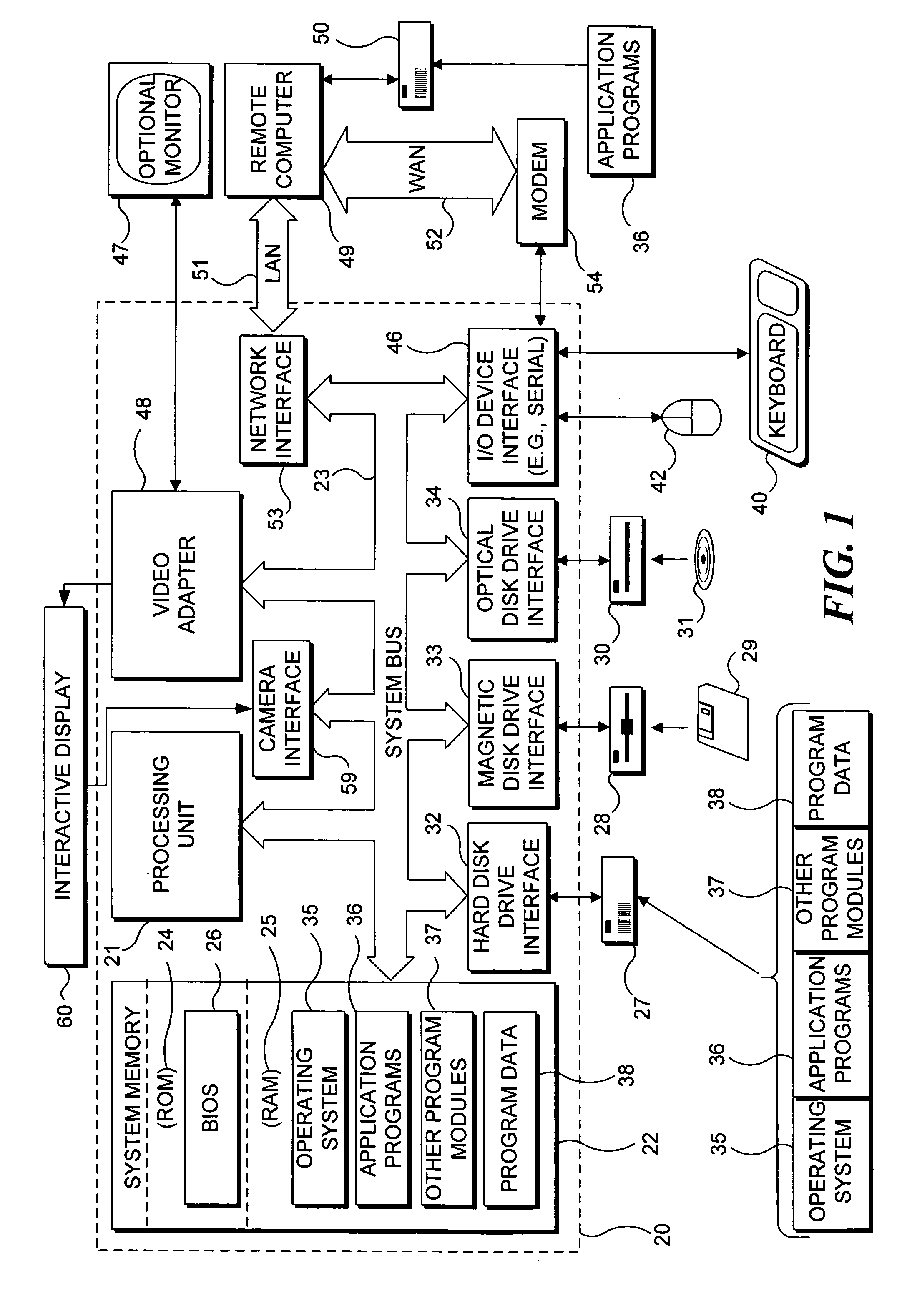
[0019] With reference to FIG. 1, an exemplary system suitable for implementing various portions of the present invention is shown. The system includes a general purpose computing device in the form of a conventional PC 20, provided with a processing unit 21, a system memory 22, and a system bus 23. The system bus couples various system components including the system memory to processing unit 21 and may be any of several types of bus structures, including a memory bus or memory controller, a peripheral bus, and a local bus using any of a variety of bus architectures. The system memory includes read only memory (ROM) 24 and random access memory (RAM) 25. A basic input / output system 26 (BIOS), containing the basic routines that help to transfer information between elements within the PC 20, such as during start up, is stored in ROM 24. PC 20 further includes a hard disk drive 27 for reading from and writing to a hard disk ...


PUM


Abstract

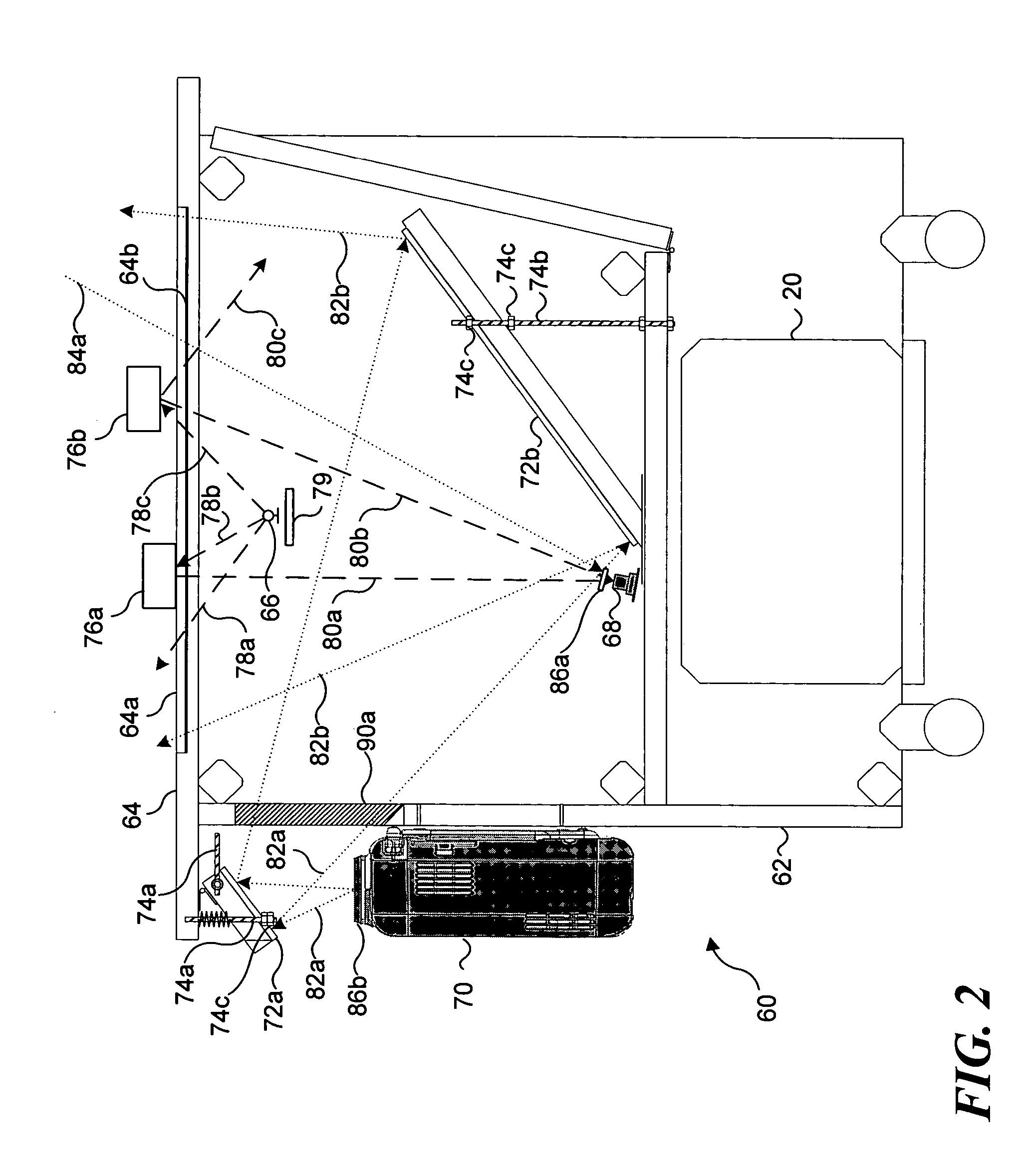
In an interactive display table that uses infrared (IR) light to detect an object on an interactive display surface, IR light sources within the table are controlled in response to the level of ambient IR light passing through the interactive display surface. Light from the IR light sources that is reflected the regions disposed inside the table and peripherally around the interactive display surface is captured in an image that also includes the ambient IR light passing through the interactive display surface. A signal corresponding to the image is processed, so that the relative levels of the IR light can be compared. The IR light sources are then controlled so that the level of IR light reflected from the regions exceeds the level of ambient IR light by at least a predefined amount.

Description

FIELD OF THE INVENTION [0001] The present invention is generally directed to controlling an intensity of light produced by a light source in response to ambient light, and more specifically, pertains to controlling an infrared (IR) light source used for detecting objects placed adjacent to a interactive display surface in response to IR light intensity in ambient light. BACKGROUND OF THE INVENTION [0002] Several interactive displays are known in the prior art. For example, a user interface platform was developed in the MIT Media Lab, as reported by Brygg Ullmer and Hiroshi Ishii in “The metaDESK: Models and Prototypes for Tangible User Interfaces,”Proceedings of UIST 10 / 1997:14-17. This article describes how the metaDESK includes a near-horizontal graphical surface that is used to display two-dimensional (2D) geographical information. A computer vision system inside the desk unit (i.e., below the graphical surface) includes infrared (IR) lamps, an IR camera, a video camera, a video ...

Claims


Application Information

Patent Timeline
IPC IPC(8): G03F7/20G06F3/042
CPCG06F3/0425
Inventor YEE, DAWSON L.
Owner MICROSOFT TECH LICENSING LLC
Learn More