
Instrument and system for pharmacologic measurement and well vessel used therein
- Summary
- Abstract
- Description
- Claims
- Application Information
AI Technical Summary
Benefits of technology
Problems solved by technology
Method used
Image

Examples
embodiment 1
(Construction of Pharmacologic Measurement Instrument of Embodiment 1)
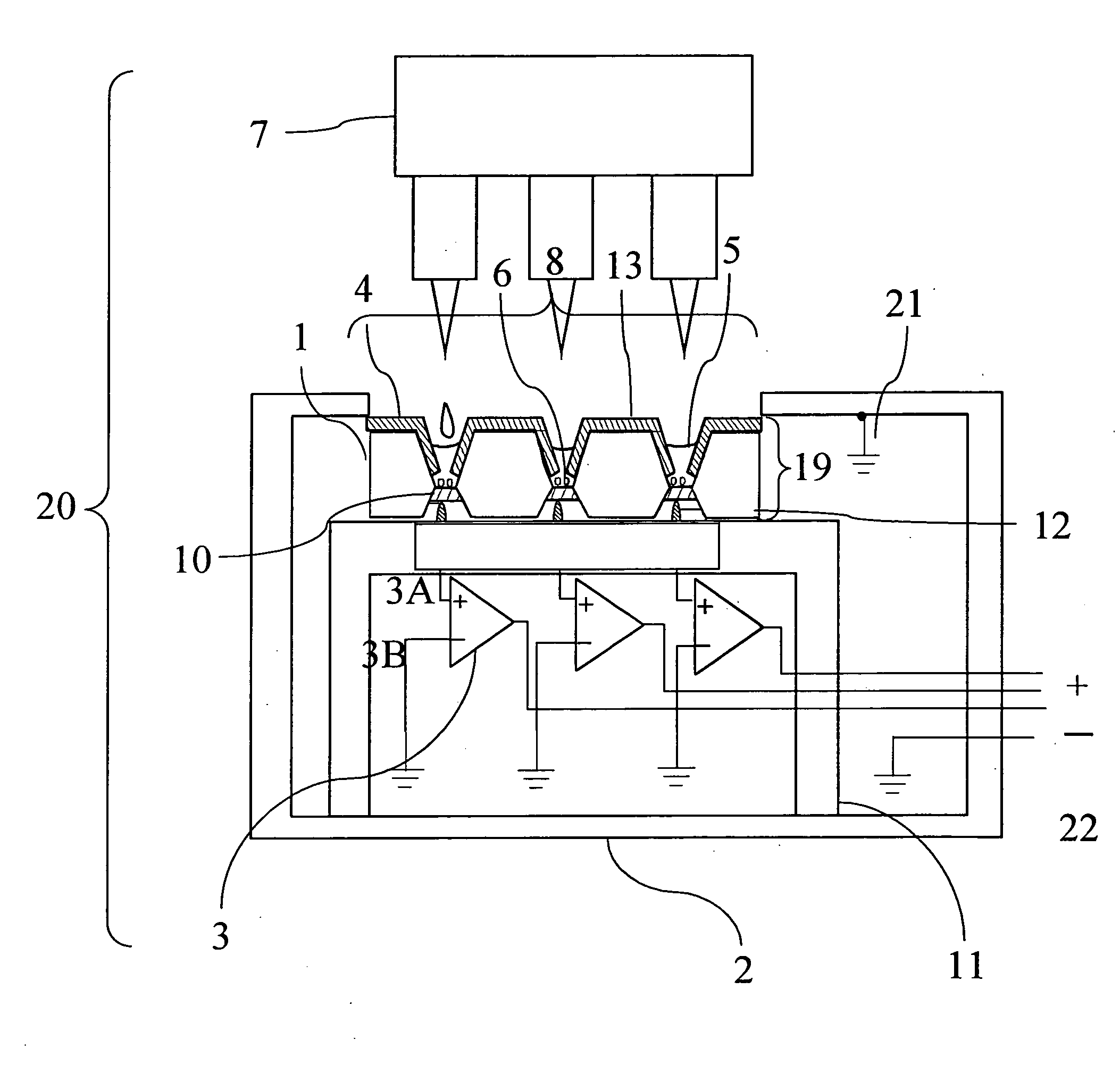
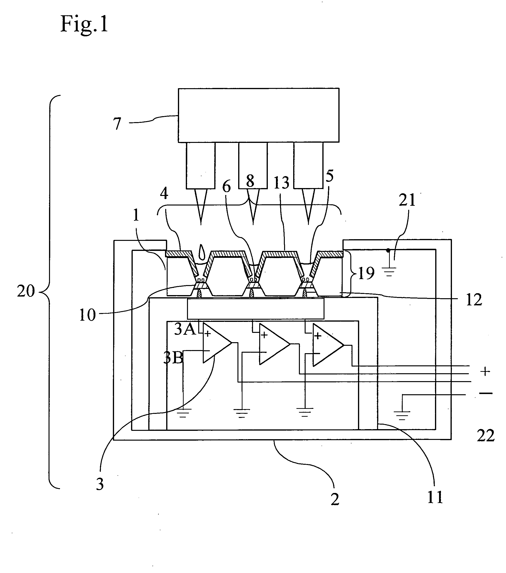
[0054]FIG. 1 is a conceptual view, as a mode, showing a construction of a pharmacologic measurement instrument 20 of a first embodiment. The pharmacologic measurement apparatus of the first embodiment has an electrical conductive box 2 having an opening section 8 at the top surface and a well vessel 19 provided in the opening section 8. The well vessel 19 may be either fixable at the opening section 8 of the electrically conductive box 2 or demountable from the opening section 8. The pharmacologic measuring instrument 20, when required, further includes: a solution injection / discharge device 7; preamplifiers (first signal amplifiers) 3 in an electrical conductive box 2; a base substrate placement table 11 for fixing the well vessel 19; measuring electrodes; and contact points 12 electrically connecting the measurement electrodes 10 to respective the preamplifiers (the first signal amplifiers) 3. The number of di...
embodiment 2
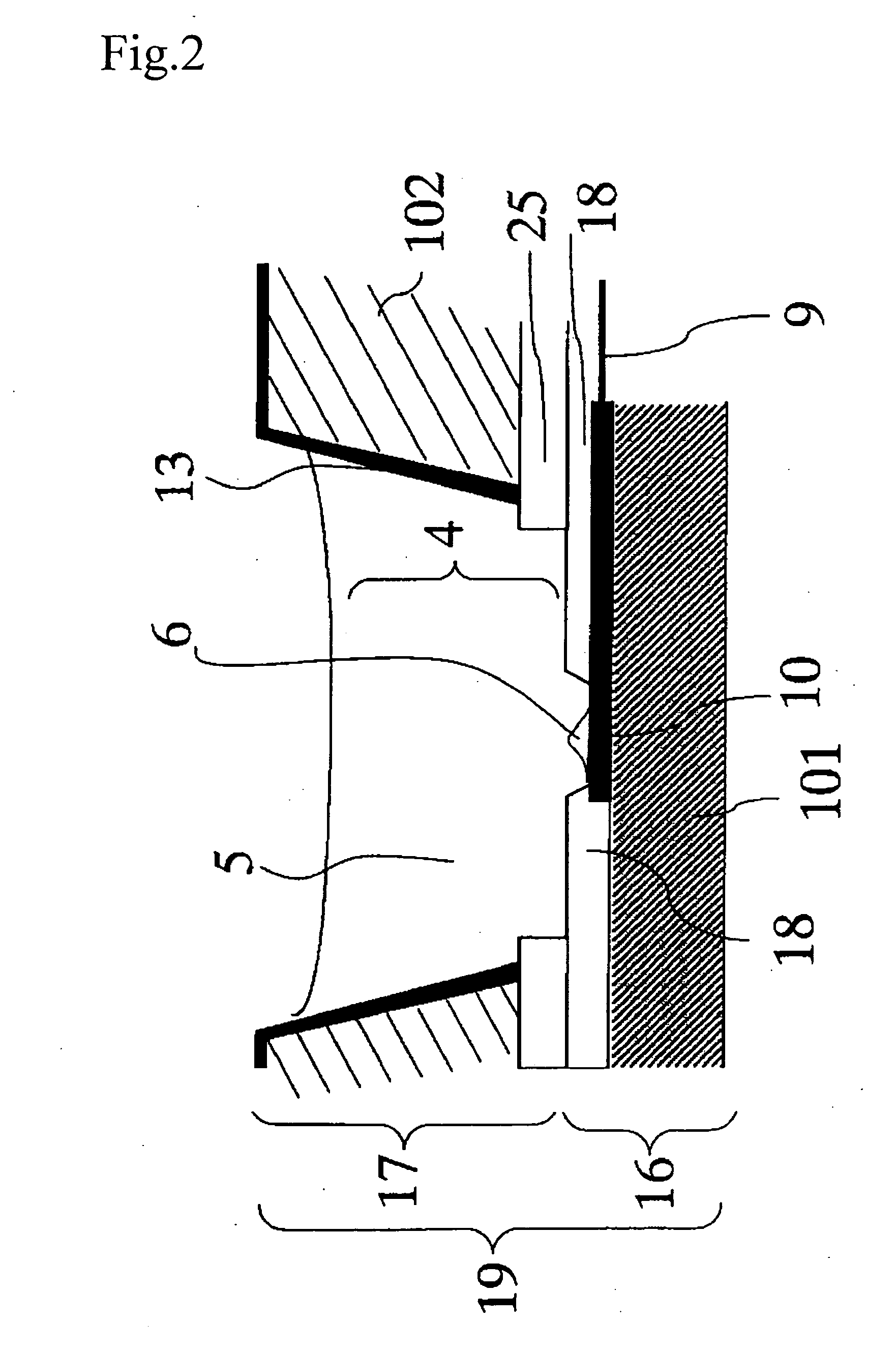
[0082] The second embodiment is related to a pharmacologic measurement instrument provided with electrodes each having a construction different from that in the first embodiment. FIG. 6 is a sectional view, as a model, showing a structure of a well vessel 19 of a pharmacologic measurement apparatus of the second embodiment. FIG. 7 is a construction in which the electrodes 10 are disposed at intersections in a square array of 6 rows and 6 columns. FIG. 8 is a sectional view taken on line C0-C1 of the well vessel of FIG. 7. A part of FIG. 8 encircled with a dotted line corresonding to a well vessel including one measurement electrode. While in FIG. 6, there is shown a well vessel 19 in which only one measurement electrode 10 is formed in the recess (frame) 4, a construction may be adopted in which plural electrodes 10 and corresponding lead lines 9 are formed in the frame 4, which is similar to that in the first embodiment. Note that since in the sensor base substrate 16 of the second...
example 1
[0091] The pharmacologic measurement instrument of a first embodiment shown in FIG. 1 was fabricated by way of trial as Example 1. The pharmacologic measurement instrument of a conventional construction shown in FIG. 10 was fabricated by way of trial as Comparative Example 1. Experiments to investigate characteristics of the electrodes were conducted on Example 1 and Comparative Example 1.
(Fabrication of Pharmacologic Measurement Instrument)
[0092] First of all, description will be given of a fabrication method for the sensor base substrate 16 and the solution holding section 17 of the well vessel 19.
[0093] The sensor base substrates 16 of Example 1 and Comparative Example 1 were fabricated using a 4 inch SOI wafer as base substrate material. A front surface of the base substrate was dry etched to form a group of through holes with RIE. A back surface of thereof was etched by anisotropic wet etching using TMAH (tetramethyl ammonium) to thereby complete through holes between the f...
PUM
| Property | Measurement | Unit |
|---|---|---|
| Temperature | aaaaa | aaaaa |
| Electrical conductivity | aaaaa | aaaaa |
| Diameter | aaaaa | aaaaa |
Abstract
Description
Claims
Application Information