Materials and methods of derivitzation of electrodes for improved electrical performance of OLED display devices

a technology of oled display device and electrode, which is applied in the direction of instruments, cell components, discharge tube luminescnet screens, etc., can solve the problems of insufficient electrical conductivity of organic layers, increased weight and additional manufacturing costs, and many problems of existing organic light emitting devices, etc., to facilitate molecular interaction and stability, and enhance the effect of emission si

Inactive Publication Date: 2005-12-22
DYNAMIC ORGANIC LIGHT
View PDF1 Cites 16 Cited by
  • Summary
  • Abstract
  • Description
  • Claims
  • Application Information

AI Technical Summary

Benefits of technology

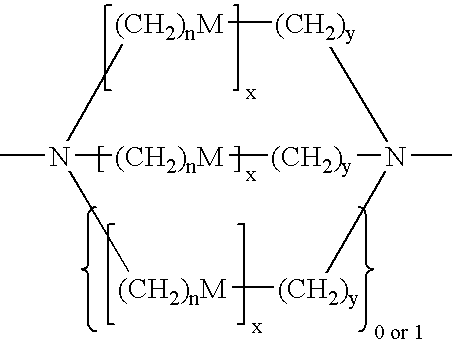
[0009] Travel of electrical energy between electrode modificationing molecules can occur when portions of two different electrode modificationing molecules, for example, electrode modification groups, are linked together. Two-dimensional transport of electrical energy allows electrical energy transfer to occur even if a defect is present in a layer of light emitting molecules. The electrode modificationing molecule also comprises a molecular compatibility group bonded to the second end of the electrode modification group. The molecular recognition group acts as a nucleation site for deposited small molecule materials utilized in state of the art small molecule OLED devices and in the same capacity with state of the art polymeric PLED devices. A molecular recognition group can be a ligand which facilitates molecular interaction and stability with applied small molecule OLED or polymeric PLED materials components. The molecular recognition site in the capacity of a ligand can coordinate an emissive metal ion, preferably a lanthanide metal, which would act as a dopant enhancing emission site in small molecule OLED devices.

Problems solved by technology

However, existing organic light emitting devices often suffer from a number of problems.
The requirement of multiple organic layers can result in added weight and additional manufacturing costs.
As a result of such random orientation, electrical conductivity of the organic layers can be inadequate, and charged species can travel relatively great distances in three dimensions along the randomly oriented polymeric materials before reaching a fluorescent or phosphorescent species that can emit light.
However, the electric field density can lead to thermal breakdown or instability of the organic layers.

Method used


Image

  • Materials and methods of derivitzation of electrodes for improved electrical performance of OLED display devices
  • Materials and methods of derivitzation of electrodes for improved electrical performance of OLED display devices
  • Materials and methods of derivitzation of electrodes for improved electrical performance of OLED display devices

Examples


Embodiment Construction

[0014] Various embodiments of the invention relate to electrode modificationing molecules and organic light emitting devices including such light emitting molecules. Organic light emitting devices in accordance with various embodiments of the invention can offer a number of advantages, such as, for example, improved transport of electrical energy, improved robustness and thermal stability, improved visual characteristics, reduced energy requirements, reduced weight and lower manufacturing costs.

Definitions:

[0015] The following definitions apply to some of the elements described with regard to some embodiments of the invention. These definitions may likewise be expanded upon herein.

[0016] As used herein, “array” means an arrangement of more than one electrode modificationing molecule or pixel element. Arrays can be ordered, where the relative spacing between electrode modificationing molecules or pixel elements and / or relative alignment of electrode modificationing molecules or p...


PUM

PropertyMeasurementUnit
angleaaaaaaaaaa
angleaaaaaaaaaa
wavelengthsaaaaaaaaaa

Abstract

A method of derivitization of electrode surfaces in small molecule or polymeric organic light emitting diodes (OLED) and display devices employing the same are presented whereby and assemblage of molecular wires are employed. The assemblage of molecular wires facilitates the transportation of electrical energy from an inorganic electrode, such as indium-tin-oxide or doped silica, to organic layers of compounds and composites / polymers, found in conventional OLED materials and construction. Thereby, devices made in accordance with the invention have dramatically improved work function characteristics including a dramatic increase in the external quantum efficiency. In addition, the molecular wire components further stabilize the mechanical properties of OLED materials at the wire OLED interface.

Description

CROSS-REFERENCE TO RELATED APPLICATIONS [0001] This application claims the benefit of U.S. Provisional Application Ser. No. 60 / 581,827, filed on Jun. 21, 2004, the disclosure of which is incorporated herein by reference to the extent not inconsistent with the disclosure herein.BACKGROUND OF THE INVENTION [0002] 1. Technical Field [0003] The invention relates to organic light emitting devices. More particularly, the present invention relates to organic light emitting devices utilizing molecular compatibility between inorganic electrode surfaces and OLED and PLED materials. [0004] 2. Description of Related Art [0005] Organic light emitting devices (OEDs) have begun to attract great interest for a multiplicity of applied uses. For example, attempts have been made to incorporate organic light emitting devices in display devices. Organic light emitting devices can potentially offer a number of advantages over other types of display technologies. In particular, compared with certain types...

Claims


Application Information

Patent Timeline
Patent Type & Authority Applications(United States)
IPC IPC(8): G09G3/00H01L51/00H01L51/50H01L51/52H01M4/60H05B33/12
CPCB82Y10/00B82Y20/00B82Y30/00H01L51/0003H01L51/0075H01L51/0089Y02E10/549H01L51/0096H01L51/105H01L51/5088H01L51/5203H01L51/5206H01L51/0094H10K71/12H10K85/701H10K85/351H10K77/10H10K85/40H10K10/84H10K50/17H10K50/81H10K50/805
Inventor CABALLERO, GABRIEL J.
Owner DYNAMIC ORGANIC LIGHT
Why Eureka
Try Eureka