Systems and methods for hypotension

a technology of system and method, applied in the field of medical devices and methods, can solve the problems of reducing blood circulation, reducing blood circulation, and drug therapy not always effective in treating certain patients' arrhythmias

Inactive Publication Date: 2005-12-22
CARDIAC PACEMAKERS INC
View PDF40 Cites 135 Cited by
  • Summary
  • Abstract
  • Description
  • Claims
  • Application Information

AI Technical Summary

Problems solved by technology

Such arrhythmias result in diminished blood circulation.
However, drug therapy is not always effective for treating arrhythmias of certain patients.
Such too-fast heart rhythms also cause diminished blood circulation because the heart isn't allowed sufficient time to fill with blood before contracting to expel the blood.
Such pumping by the heart is inefficient.
One problem faced by some patients is hypotension, that is, low blood pressure.
Hypotension can result in dizziness, sometimes referred to as presyncope.
One cause of hypotension is an excess shifting of blood in the circulatory system toward the extremities (arms and legs) and away from vital organs in the patient's head and thorax.
However, hypotension may also have causes other than changes in posture.
For example, maintaining the same posture for an extended period of time (e.g., sitting erect during an intercontinental airplane flight) may also cause hypotension.
For ex...

Method used


Image

  • Systems and methods for hypotension
  • Systems and methods for hypotension
  • Systems and methods for hypotension

Examples


example 1

Electrode Configuration and Top-Level Block Diagram

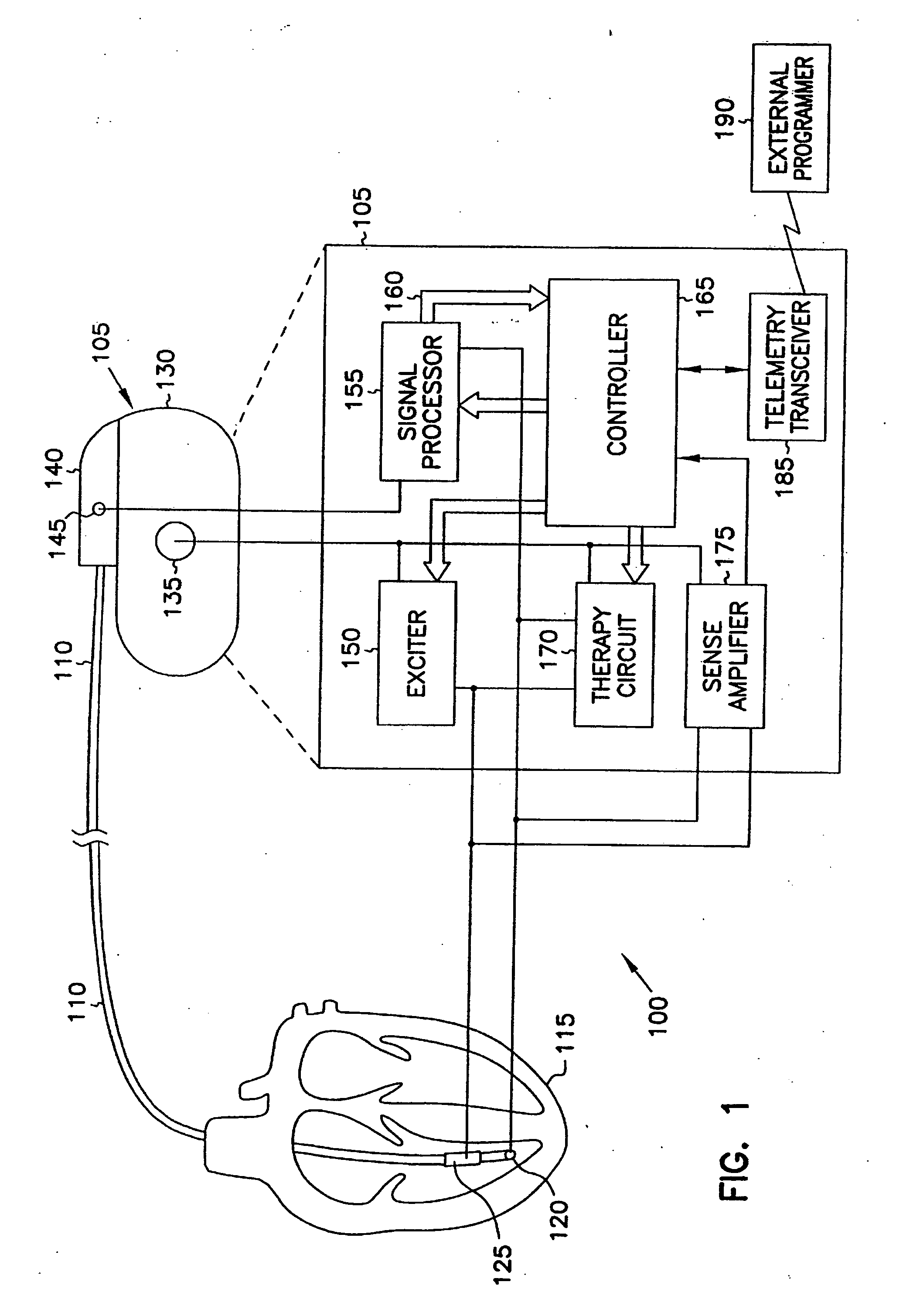
[0030]FIG. 1 is a schematic / block diagram illustrating generally, by way of example, but not by way of limitation, one embodiment of a cardiac rhythm management system 100 according to the present invention. In this embodiment, system 100 includes, among other things, cardiac rhythm management device 105 and leadwire (“lead”) 110 for communicating signals between device 105 and a portion of a living organism, such as heart 115. Embodiments of device 105 include, among other things, bradycardia and antitachycardia pacemakers, cardioverters, defibrillators, combination pacemaker / defibrillators, drug delivery devices, and any other implantable or external cardiac rhythm management apparatus capable of providing therapy to heart 115. System 100 may also include additional components such as, for example, a remote programmer 190 capable of communicating with device 105 via a transmitter or receiver, such as telemetry transceiver 185.

[0...

example 2

[0072]FIG. 11 is a schematic / block diagram example of portions of a cardiac rhythm management system 1100 and portions of an environment in which it is used. In this example, system 1100 includes, among other things, a cardiac rhythm management device 1102 and leadwire (“lead”) 1104, which is coupled to device 1102 for communicating one or more signals between device 1102 and a portion of a living organism or other subject, such as heart 1106. Examples of device 1102 include, among other things, bradycardia and antitachycardia pacemakers, cardioverters, defibrillators, combination pacemaker / defibrillators, drug delivery devices, and any other implantable or external cardiac rhythm management apparatus capable of providing therapy to heart 1106. System 1100 may also include additional components such as, for example, an external or other remote interface 1108 capable of communicating with device 1102.

[0073] In this example, device 1102 includes, among other things, a microprocessor ...

example 3

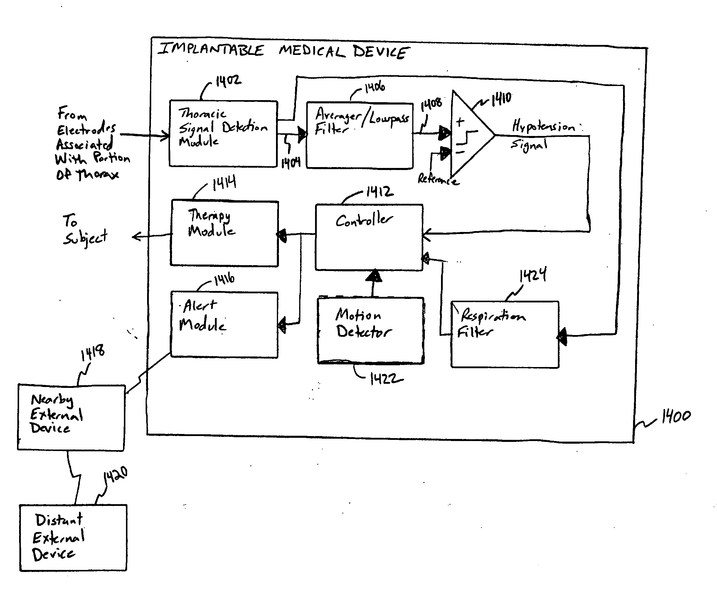
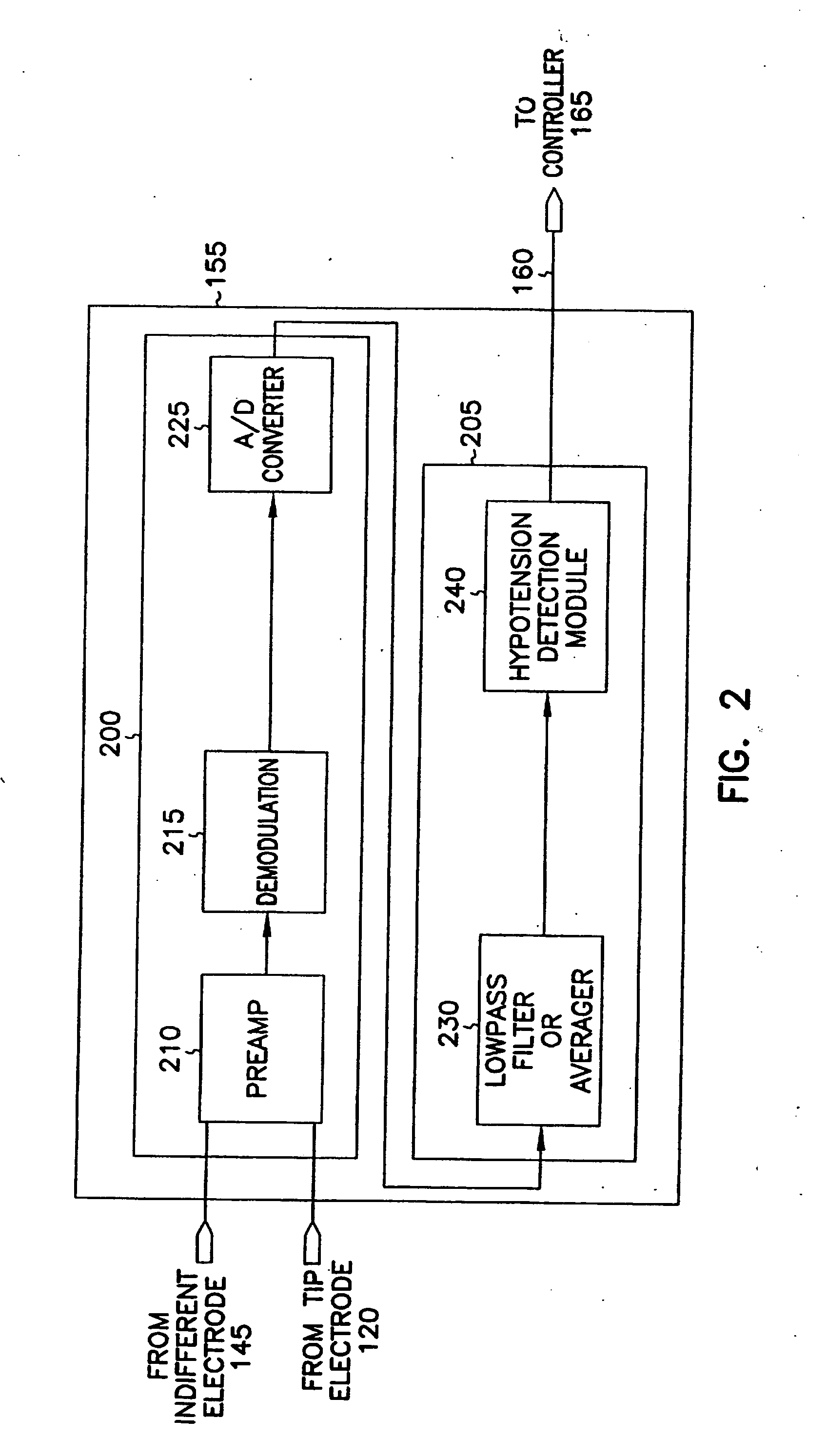
[0087]FIG. 14 is a block diagram illustrating generally portions of an implantable medical device 1400 that receives a thoracic impedance signal from electrodes associated with a portion of a subject's thorax. The thoracic impedance signal is received at thoracic signal detection module 1402. In this example, the resulting detected thoracic signal output at 1404 is received at an input of the averager / lowpass filter 1406, which attenuates frequency components of the detected thoracic impedance signal that are not indicative of hypotension (e.g., respiration, cardiac stroke components), and which passes or amplifies frequency components of the detected thoracic impedance signal that are indicative of hypotension. The resulting signal is output at node 1408 to a comparator circuit 1410, where it is compared to a reference. The comparator circuit 1410 outputs a resulting signal indicating whether or the degree to which hypotension is present.

[0088] This hypotension signal is received ...


PUM


Abstract

This document discusses, among other things, systems and methods that detect hypotension based on a measurement of thoracic impedance. It also provides an alert, a logging, or a therapy to treat the hypotension. Examples of anti-hypotension therapies include, among other things, pacing therapy, neural stimulation therapy, drug infusion therapy, or gene therapy.

Description

CROSS-REFERENCE TO RELATED APPLICATIONS [0001] This patent application is a continuation-in-part of Daum U.S. patent application Ser. No. 09 / 879,665, filed on Jun. 12, 2001, entitled “CARDIAC RHYTHM MANAGEMENT SYSTEM ADJUSTING RATE RESPONSE FACTOR FOR TREATING HYPOTENSION,” and assigned to Cardiac Pacemakers, Inc., which, in turn, is a continuation-in-part of Scheiner et al. U.S. patent application Ser. No. 09 / 832,365, filed on Apr. 10, 2001, entitled “CARDIAC RHYTHM MANAGEMENT SYSTEM FOR HYPOTENSION,” and assigned to Cardiac Pacemakers, Inc., and the disclosure of each of the above referenced patent applications is incorporated herein by reference in its entirety. [0002] This patent application is also related to Libbus et al. U.S. patent application Ser. No. 11 / 124,791 (Attorney Docket 279.780US1), entitled METHOD AND APPARATUS FOR CONTROLLING AUTONOMIC BALANCE USING NEURAL STIMULATION, filed on May 9, 2005, which is assigned to Cardiac Pacemakers, Inc., and which is incorporated ...

Claims


Application Information

Patent Timeline
IPC IPC(8): A61N1/36A61N1/365
CPCA61N1/3605A61N1/36542A61N1/36521A61N1/3625
Inventor DAUM, DOUGLAS R.SCHEINER, AVRAM
Owner CARDIAC PACEMAKERS INC
Why Eureka
Try Eureka