Vibration information transmission apparatus and vibration monitoring/analyzing system

Inactive Publication Date: 2005-12-29
SHINKAWA SENSOR TECH
View PDF10 Cites 23 Cited by
  • Summary
  • Abstract
  • Description
  • Claims
  • Application Information

AI Technical Summary

Benefits of technology

[0021] By transmitting the trigger signal for use in the synchronous measurement in correspondence with the reference position in the rotation phase of the rotatin

Problems solved by technology

Thus there is an increase in the number of the electric wires and in the amount of the wiring work.
Further owing to the increa

Method used


Image

  • Vibration information transmission apparatus and vibration monitoring/analyzing system
  • Vibration information transmission apparatus and vibration monitoring/analyzing system
  • Vibration information transmission apparatus and vibration monitoring/analyzing system

Examples


Embodiment Construction

[0028] The embodiments of the present invention will be described below with reference to the drawings.

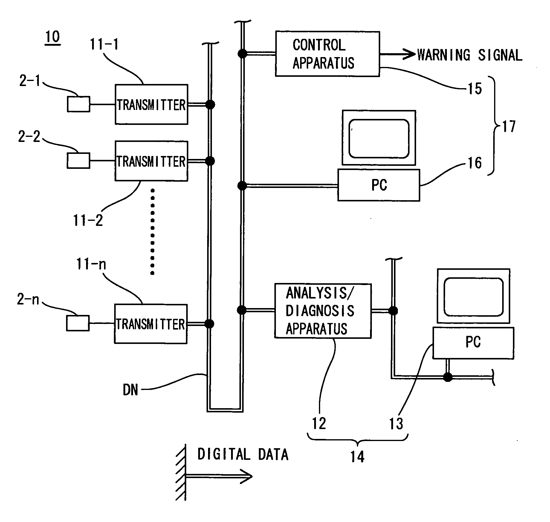
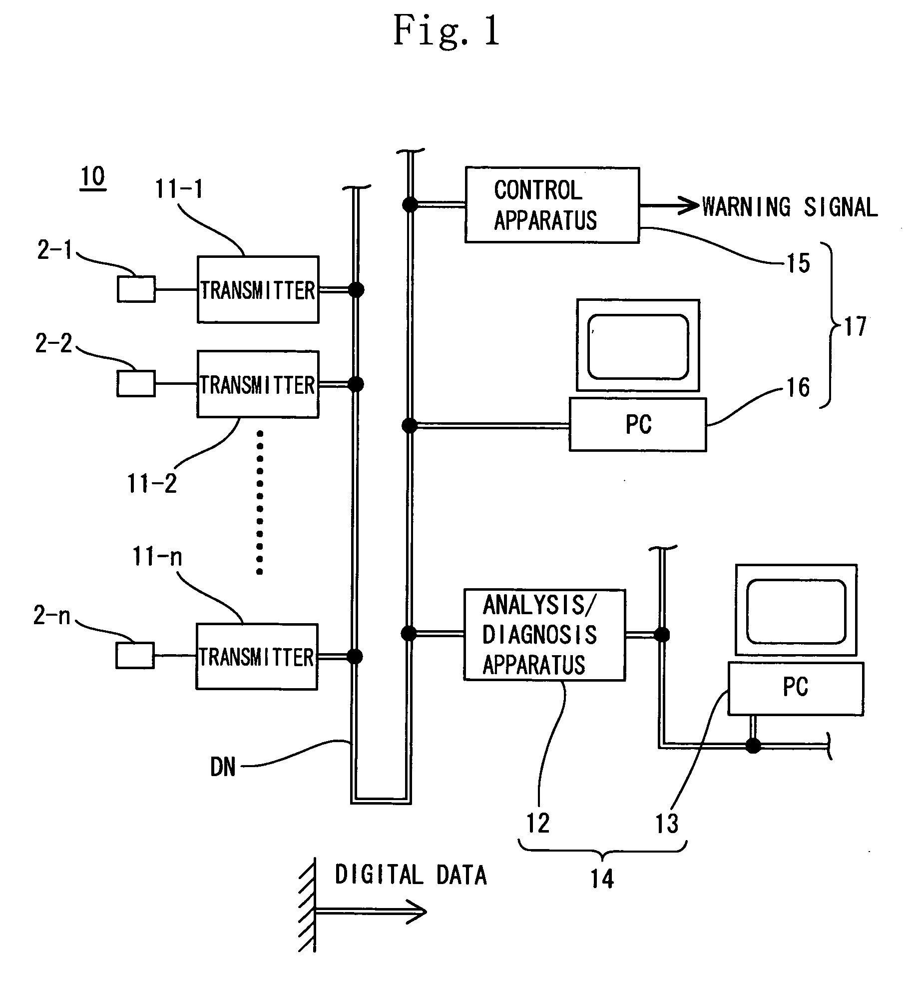
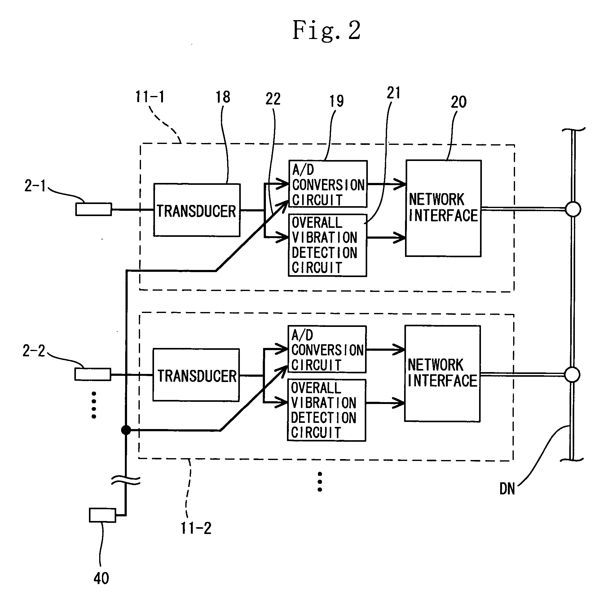
[0029] As shown in FIG. 1, a vibration monitoring / analyzing system 10 of an embodiment has vibration sensors 2-1 to n installed on a rotating machine to be diagnosed, transmitters 11-1 to n connected individually at 1:1 with the vibration sensors 2-1 to n, a digital network (filed bus) DN connected with each of the transmitters 11-1 to n, an analysis / diagnosis means 14 connected with the digital network DN, and a vibration monitoring means 17 connected with the digital network DN.

[0030] As shown in FIG. 3, a rotating machine 30 has rotors 31 mounted on a rotary shaft 32 by spacing them at certain intervals. The vibration sensors 2-1 to n are installed on a bearing portion of each of the rotors 31. A sensor 40 serving as a means for generating a synchronizing trigger signal is installed on the surface of one rotor 31.

[0031] As the vibration sensors 2-1 to n and the sensor 40, a n...


PUM


Abstract

A vibration information transmission apparatus for improving efficiency of field wiring of a vibration monitoring/analyzing system includes transmitters (11-1 to n) for converting vibration information from vibration sensors (2-1 to n) for detecting vibration of an object to be measured, into an electric signal and outputting the electric signal to a digital network (DN). The transmitters (11-1 to n) includes in the same casing, a transducer circuit (18) for converting the vibration information from the vibration sensors (2-1 to n) into an analog electric signal, an A/D conversion circuit (19) for converting the analog electric signal from the transducer circuit (18) into a digital signal, and a network interface (20) for outputting the digital signal from the A/D conversion circuit (19) to the digital network (DN).

Description

TECHNICAL FIELD [0001] The present invention relates to a vibration information transmission apparatus and a vibration monitoring / analyzing system. More particularly the present invention is intended to reduce the amount of a wiring work which is made in a field (site) for a system for analyzing vibrations of rotating machines such as a generator, a turbine, a fan, and a pump. BACKGROUND ART [0002] As shown in FIG. 6, a vibration monitoring / analyzing system 1 of a rotating machine conventionally provided has a plurality of vibration sensors 2-1 to n installed on a bearing portion of the rotating machine, transducer circuits 3-1 to n for converting sensor output signals which are vibration information transmitted thereto from the vibration sensors 2-1 to n into analog electric signals proportional to vibration values, a vibration monitor 4 for displaying the analog electric signals transmitted thereto from the transducer circuits 3-1 to n and monitoring abnormal vibrations and giving...

Claims


Application Information

Patent Timeline
IPC IPC(8): G01H1/00G01H11/06G01H17/00G01M7/02G01M99/00
CPCG01M7/025G01H1/003
Inventor BODA, SHINGOMAEDA, HIROYUKI
Owner SHINKAWA SENSOR TECH
Why Eureka
Try Eureka