Hydraulic control valve and power steering apparatus using the same
a technology of hydraulic control valve and power steering device, which is applied in the direction of multiple way valve, mechanical apparatus, transportation and packaging, etc., can solve the problems of sudden discontinuity of hydraulic characteristics, unstable oil pressure characteristics in a region where the flow rate to be controlled is minimal and is smaller than the conventional small flow rate, and discontinuous steering torqu
- Summary
- Abstract
- Description
- Claims
- Application Information
AI Technical Summary
Benefits of technology
Problems solved by technology
Method used
Image
Examples
first embodiment
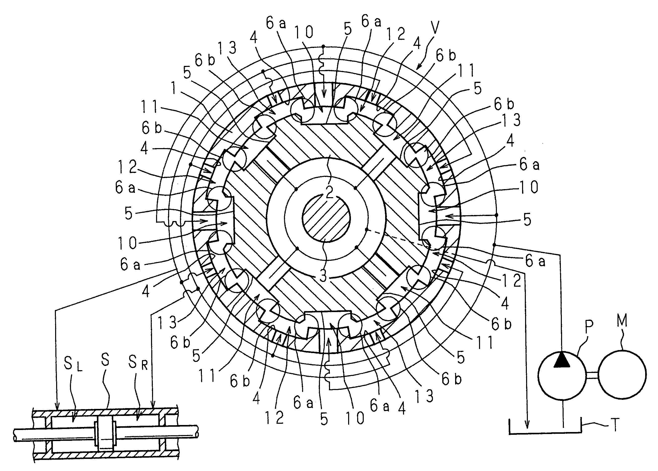
[0056]FIG. 7 is a schematic transverse sectional view showing a first embodiment of a hydraulic control valve according to the present invention, together with a hydraulic circuit of a power steering apparatus.
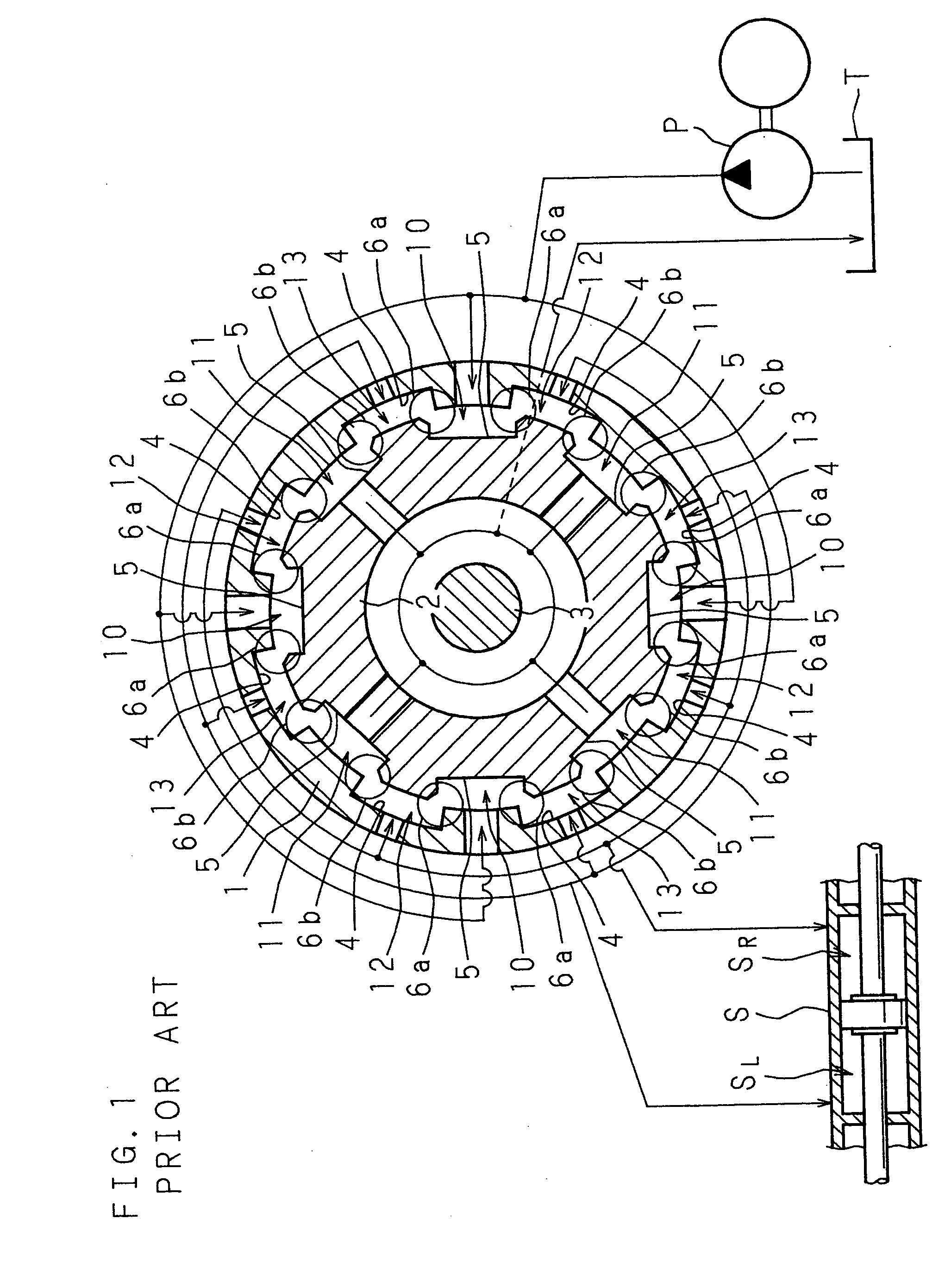
[0057] In FIG. 7, a numeral 1 represents a valve body, and a numeral 2 represents a valve spool. Basic structures of these valve body 1 and valve spool 2 are the same as the conventional ones shown in FIG. 1. Eight first oil grooves 4, 4, . . . having equal widths are parallelly disposed in an inner peripheral surface of the cylindrical valve body 1 at equal distances from one another in the circumferential direction. Eight second oil grooves 5, 5, . . . are parallelly disposed in an outer peripheral surface of the thick and cylindrical valve spool 2 having the outer diameter which is substantially equal to the inner diameter of the valve body 1 at equal distances in the circumferential direction.
[0058] The valve spool 2 is relatively rotatably fitted into the valve body 1 c...
second embodiment
[0079]FIG. 9 is a schematic transverse sectional view showing a second embodiment of a hydraulic control valve according to the present invention, together with a hydraulic circuit of a power steering apparatus.
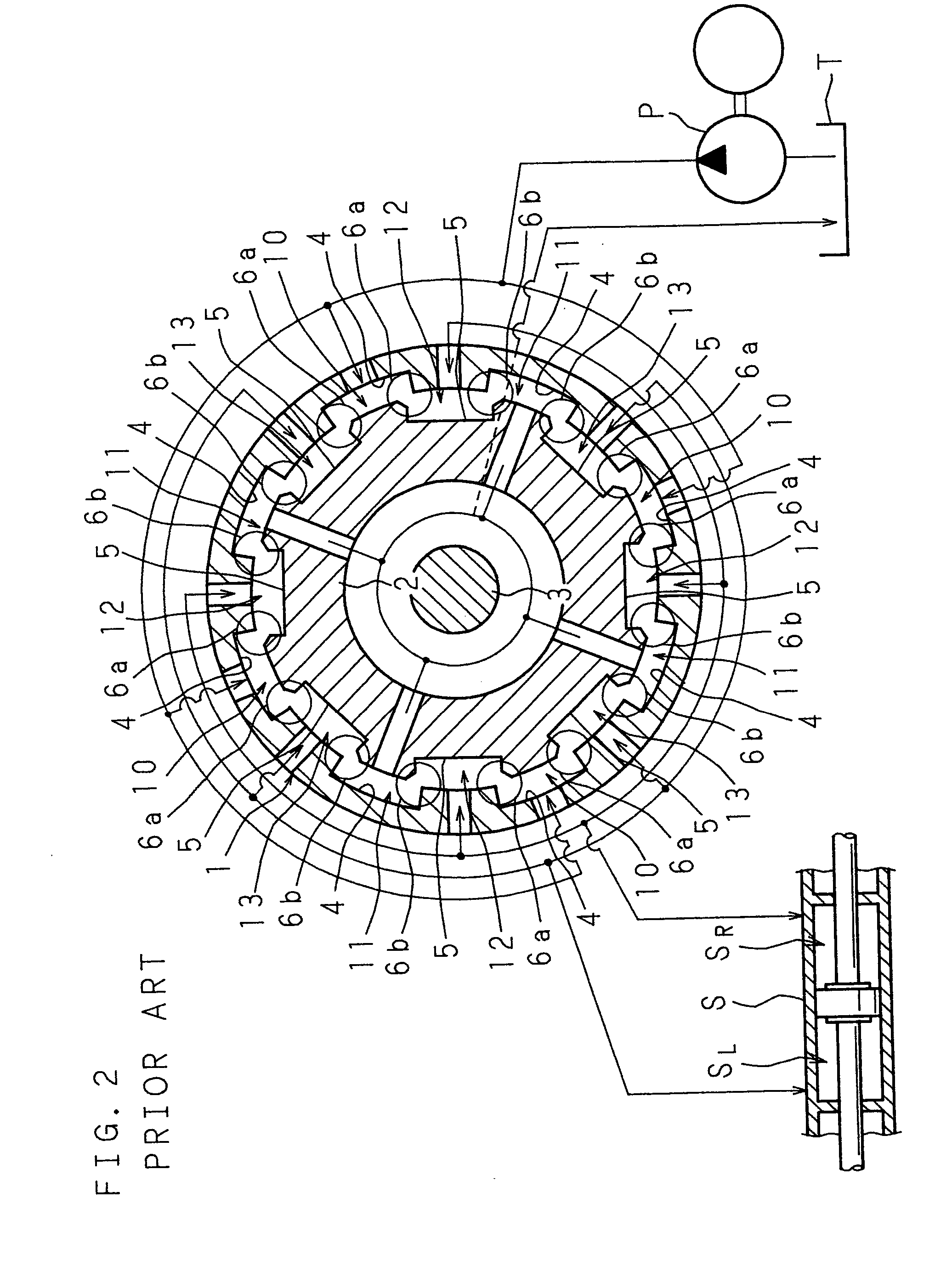
[0080] This hydraulic control valve V of the second embodiment is basically the same as the conventional structure shown in FIG. 2. Corner portions of the second oil grooves 5, 5 facing the throttle portions 6b, 6b between the oil discharge chamber 11 and the first and second oil feed chambers 12, 13 are provided with the chamfer portions 7, 7 for adjusting the throttle area, and corner portions of the second oil grooves 5, 5 facing the throttle portions 6a, 6a between the oil supply chamber 10 and the first and second oil chambers 12, 13 are not provided with the chamfer portions for adjusting the throttle area. Therefore, the flow rate is controlled by the four throttle portions 6b, 6b, . . . provided with the chamfer portions 7, 7. Other structure and operation are the sa...
third embodiment
[0086]FIGS. 11A and 11B are explanatory views of operation of an oil feed chamber, an oil supply chamber, and an oil discharge chamber shown in straightly developed manner, which are arranged along a fitted peripheral surfaces of a valve body and a valve spool of the third embodiment in the hydraulic control valve of the present invention
[0087]FIG. 11A shows a state (neutral state) in which the relative angular displacement is not generated between the valve body 1 and the valve spool 2. FIG. 11B shows a state in which the steering wheel is operated and the relative angular displacement is generated between the valve body 1 and the valve spool 2.
[0088] The hydraulic control valve of the third embodiment is basically the same as the first embodiment shown in FIGS. 7, 8A, and 8B. Corner portions of the first oil grooves 4 facing the throttle portions 6a, 6a between the oil supply chamber 10 and the first and second oil feed chambers 12, 13 are provided with the chamfer portions 7, 7...
PUM
 Abstract
Description
Claims
Application Information
 - R&D
- Intellectual Property
- Life Sciences
- Materials
- Tech Scout
- Unparalleled Data Quality
- Higher Quality Content
- 60% Fewer Hallucinations
Browse by: Latest US Patents, China's latest patents, Technical Efficacy Thesaurus, Application Domain, Technology Topic, Popular Technical Reports.
© 2025 PatSnap. All rights reserved.Legal|Privacy policy|Modern Slavery Act Transparency Statement|Sitemap|About US| Contact US: help@patsnap.com


