Process for cutting an optical fiber

a technology of optical fibers and cutting tools, applied in the field of cutting optical fibers, can solve the problems of time-consuming and, therefore, expensive, approach to mechanically cleaving and polishing optical fibers, and the angle of the end face of the optical fiber is generally limited to less than 15°, and achieves high degree of control, suitable results, and unprecedented accuracy

Inactive Publication Date: 2005-12-29
TE CONNECTIVITY CORP
View PDF2 Cites 29 Cited by
  • Summary
  • Abstract
  • Description
  • Claims
  • Application Information

AI Technical Summary

Benefits of technology

[0007] The present invention provides an approach for preparing the end face of a fiber which avoids the shortcomings of the prior art by using a laser to cut and polish the end face simultaneously. According to the present invention, the fiber is held in a holding and positioning device and the fiber is then cut or machined by means of a laser beam moving relative to the fiber. As a result, a fiber end face can be prepared accurately with a predetermined angle or shape and with surface uniformity such that additional machining of the fiber end face is unnecessary.
[0010] Aside from just complex end face geometries, the present invention also provides for the end shaping of individual fibers in a ribbon cable. In one particular preferred embodiment, the laser is used to cut each fiber of a ribbon cable at an angle other than perpendicular to the optical axis, thus, achieving a saw tooth configuration. In another preferred embodiment, the fibers of a ribbon cable which is to be optically coupled to a waveguide or other device are configured as they would be in the device, for example, fanned out, and then each is laser cut to the desired end face angle. Thus, a complex arrangement, in which each fiber of the ribbon cable must be cut at a different angle and / or to a different length due to the fibers fanning out, is made easy.
[0011] Aside from the flexibility offered by the approach of the present invention in preparing fibers of any desired end face geometry, the laser's sublimatation of the glass, rather than a mechanical cut, offers a number of advantages and distinctions over the prior art. For example, ablation of the glass, as opposed to mechanical cleaving, provides for a smooth end face which generally requires little if any subsequent polishing. Furthermore, a laser cut end face tends to have rounded edges rather than sharp edges. This rounding occurs because the fiber material becomes somewhat molten in the vicinity adjacent the cut, and the surface tension of the glass pulls across the edge, thereby causing the edge to flatten or become rounded. On the other hand, the end face of a polished fiber has sharp edges since the fiber does not become fluid during the polishing step to the extent that the surface tension of the fiber material has any significant effect. Such differences in end face geometry are significant. For example, the rounded edges formed by laser cleaving are better suited for V-groove alignment applications since the rounded edges glide along the V-groove rather than schriving it as a sharp edge might and potentially creating debris in the optical path.
[0012] The present invention is also able to prepare an end face with unprecedented accuracy and precession. For example, whereas former mechanical systems have typical angle tolerances of + / −0.5 μm, angle tolerances of less than + / −0.2 μm can be achieved with the process according to the invention. Additionally, the present invention offers a high degree of control over the position of the cleaved end face relative to a reference point. For example, it has been observed that a tolerance of less than + / −10 μm is achievable. Furthermore, it has been observed that the laser can cleave within 1 mm of the fiber coating with suitable results.

Problems solved by technology

For example, the multiple steps required makes this approach time-consuming, and, thus, expensive.
The approach of mechanically cleaving and polishing a fiber also tends to be limited in flexibility.
Furthermore, the angle of the end face of a fiber is generally limited to less than 15° due to the excessive forces the polishing pad imparts to the fiber as the angle increases.
Glass fiber tends to lack axial strength.
At some point, the axial force component, in combination with the torsional force component, causes the fiber tip to fracture.

Method used


Image

  • Process for cutting an optical fiber
  • Process for cutting an optical fiber
  • Process for cutting an optical fiber

Examples


Embodiment Construction

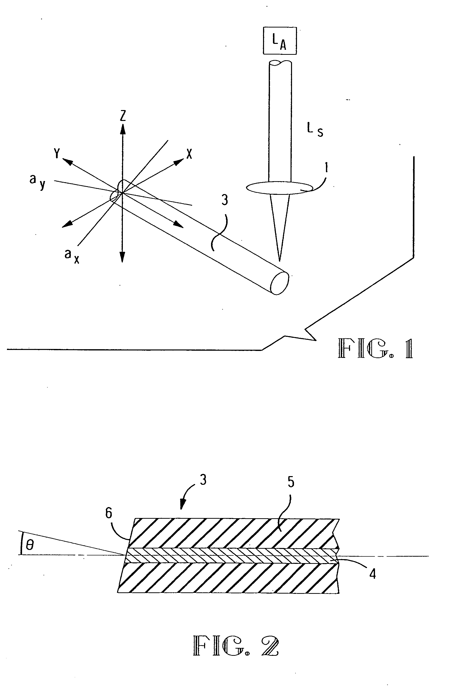
[0021] Referring to FIG. 1, a laser LA from which a laser beam LS issues is initially required for carrying out the process of cutting a fiber 3. The optical fiber 3 is a glass fiber, for example a monomode or multimode fiber. As shown in FIG. 2, the fiber 3 consists of a fiber core 4 and a fiber sheath 5 so that the light is guided substantially in the fiber core 4.

[0022] In general, any laser with a wavelength between 0.1 and 1.5 μm and 8.5 μm to 10μm can be used for producing the beam for cleaving the fibers. Suitable lasers include, for example, CO2 and excimer lasers, although a CO2 laser is preferred. CO2 lasers have proven particularly advantageous due to the high speed at which they can operate and their resultant cost effectiveness. The fiber material is removed by ablation by the CO2 laser during the cutting process, such that, rather than melting, the glass is sublimated.

[0023] Balancing the objective of delivery high energy to fiber to ablate the glass is the need to m...


PUM

PropertyMeasurementUnit
angleaaaaaaaaaa
angleaaaaaaaaaa
end face angleaaaaaaaaaa

Abstract

A process for cutting or splitting at least one optical fiber at a predetermined angle, wherein the fiber is introduced into a holding and positioning device and is cut by a pulsed laser beam.

Description

REFERENCE TO RELATED APPLICATIONS [0001] This application is a divisional of prior application Ser. No. 09 / 880,698, filed on Jun. 12, 2001, which is a continuation in part of application Ser. No. 09 / 395,352, filed on Sep. 14, 1999, and claims priority to provisional application No. 60 / 229,787 filed on Sep. 1, 2000. These applications are incorporated herein by reference in their entirety.FIELD OF THE INVENTION [0002] The invention relates to cutting one or more fibers to form angled or shaped end faces that require no polishing. BACKGROUND OF THE INVENTION [0003] Optical fibers made of glass are often used in optical transmission systems and other optical systems. The machining of the end face of these fibers plays a crucial role during the use of these monomode or multimode fibers. It is important that the end faces have a particularly uniform surface so that the transition from one fiber end to another or to an active element can be carried out with damping values which are as low...

Claims


Application Information

Patent Timeline
Patent Type & Authority Applications(United States)
IPC IPC(8): B23K26/06B23K26/16B23K26/38B23K26/40C03B37/016G02B6/25G02B6/42
CPCB23K26/0635B23K26/0639B23K26/0648B23K26/0665G02B6/4249B23K26/4075G02B6/25G02B6/30G02B6/4202B23K26/38B23K26/064B23K26/0624B23K26/40B23K2103/50
Inventor VERGEEST, HENRICUS JOZEFMARIA HULTERMANS, ANTONIUS PETRUS CORNELISSTROOBACH, PIETER
Owner TE CONNECTIVITY CORP
Why Eureka
Try Eureka