

PWM circuit control method
a technology of circuit control and control method, applied in the direction of electric controllers, ignition automatic control, instruments, etc., can solve problems such as noise generation, and achieve the effect of preventing noise generation and improving the dispersion characteristic of the higher harmonic wave componen
- Summary
- Abstract
- Description
- Claims
- Application Information
AI Technical Summary
Benefits of technology
Problems solved by technology
Method used
Image

Examples
first embodiment
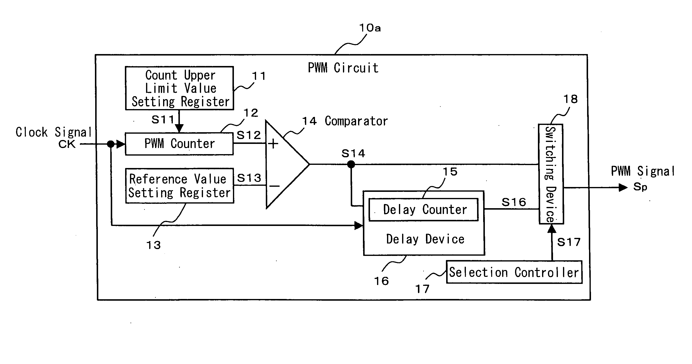
[0072]FIG. 1 is a block diagram for showing the structure of a PWM circuit 10a according to a first embodiment of the present invention.
[0073] The PWM circuit 10a comprises a count upper limit value setting register 11, a PWM counter 12, a reference value setting register 13, and a comparator 14.
[0074] The count upper limit value setting register 11 sets a count upper limit value S11 for determining a carrier period of the PWM. The PWM counter 12 performs up / down count of clock signals CK. The reference value setting register 13 sets a comparative reference value for determining the duty ratio of a PWM signal Sp. The comparator 14 compares a count value S12 counted by the PWM counter 12 and the comparative reference value S13 set by the reference value setting register 13, and generates an active PWM signal Sp when the former value exceeds the latter value.
[0075] The count value S12 counted by the PWM counter 12 is inputted to a noninverting input terminal (+) of the comparator 1...
second embodiment
[0083]FIG. 3 is a block diagram for showing the structure of a PWM circuit 10b according to a second embodiment of the present invention.
[0084] In FIG. 3, the same reference numerals as those used in FIG. 1 of the first embodiment indicate the same structural elements. Thus, the detailed description thereof will be omitted. This embodiment comprises a phase-adjusting-amount controller 20b in addition to the structural elements shown in FIG. 1. The phase-adjusting-amount controller 20b has a built-in delay time setting register 19 which can set the count value of the delay counter 15 in the delay device 16 to an arbitrary value.
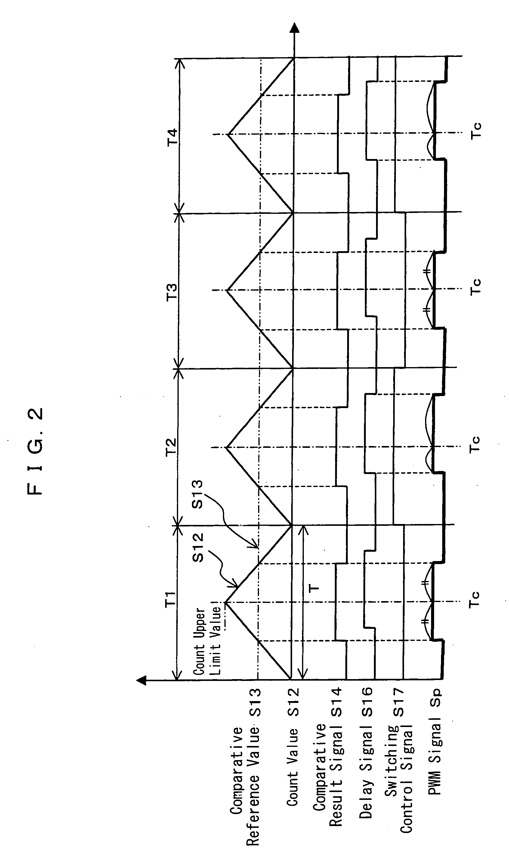
[0085]FIG. 4 is a timing chart for showing the action of the PWM circuit 10b of this embodiment. The delay time setting register 19 of the phase-adjusting-amount controller 20b sets the delay time which varies for each carrier period T. Delay time τ1, τ2, τ3 of the delay signal S16 for the comparative result signal S14 is changed for each carrier period T. T...
third embodiment
[0086]FIG. 5 is a block diagram for showing the structure of a PWM circuit 10c according to a third embodiment of the present invention.
[0087] In FIG. 5, the same reference numerals as those used in FIG. 1 showing of the first embodiment indicate the same structural elements. Thus, the detailed description thereof will be omitted. This embodiment comprises a phase-adjusting-amount controller 20c in addition to the structural elements shown in FIG. 1. The phase-adjusting-amount controller 20c has a built-in random-number generating circuit 21 which can set the count value of the delay counter 15 in the delay device 16 as random numbers. The random-number generating circuit 21 calculates an appropriate delay time based on the count upper limit value S11 of the count upper limit value setting register 11 and the comparative reference value S13 of the reference value setting register 13.
[0088]FIG. 6 is a timing chart for showing the action of the PWM circuit 10c of this embodiment. Th...
PUM
 Abstract
Description
Claims
Application Information