Slew rate enhancement circuitry for folded cascode amplifier

a cascode amplifier and enhancement circuit technology, which is applied in the direction of dc-amplifiers with dc-coupled stages, amplifiers with semiconductor devices/discharge tubes, and differential amplifiers, can solve the problems of reducing the slew rate, adding to the total input referred noise, and low slew rate of the two-stage folded cascode amplifier. , to achieve the effect of low cost, high slew rate and low noise amplifier

Inactive Publication Date: 2005-12-29
TEXAS INSTR INC
View PDF1 Cites 47 Cited by
  • Summary
  • Abstract
  • Description
  • Claims
  • Application Information

AI Technical Summary

Benefits of technology

[0010] It is an object of the present invention to provide a low cost, low noise amplifier having a high slew rate.

Problems solved by technology

One technique for increasing the slew rate of an amplifier is to increase the bias current of the input stage, but that has a tendency to increase the bandwidth of the amplifier and leads to a need to increase the compensation capacitance of the amplifier to improve circuit stability, which tends to decrease the slew rate.
Moreover, in the folded cascode amplifier, increasing the input stage bias current requires a commensurate increase in the second stage current (to avoid turning the second stage off, which in turn adds to the total input referred noise.
Providing both a high slew rate and a low noise level in a two stage folded cascode amplifier puts conflicting constraints on bias currents of the input stage and the second stage of the amplifier, because keeping the second stage noise contributions low generally requires keeping the operating bias currents low in the second stage.
However, that ordinarily results in a low slew rate of the two stage folded cascode amplifier.
Although there are many operational amplifier designs capable of providing high slew rates, they unfortunately have various problems, including high noise generation, high power dissipation, ineffective operation at low power supply voltages, poorly controlled operational parameters over a range of power supply voltages, and / or redundant circuitry.

Method used


Image

  • Slew rate enhancement circuitry for folded cascode amplifier
  • Slew rate enhancement circuitry for folded cascode amplifier
  • Slew rate enhancement circuitry for folded cascode amplifier

Examples


Embodiment Construction

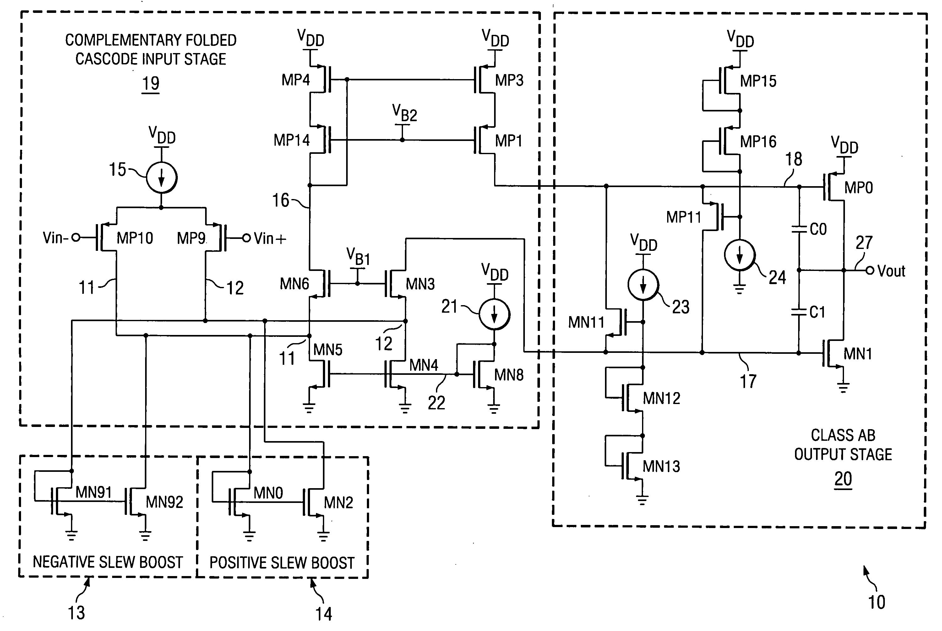
[0022] In accordance with the present invention, two current mirrors are added in parallel with the junctions between the drains of the input transistors and the sources of the corresponding cascode transistors of a two stage folded cascode amplifier. During normal operation, the two current mirrors are completely shut off and therefore are “transparent” to the two stage folded cascode amplifier. The two current mirrors also provide current gain to charge and discharge the compensation capacitors to help provide a high slew rate.

[0023] The two current mirrors are activated by “excess current” from the input transistors of the input stage caused by a large, rapid transition of the input voltage applied to gates of the input transistors. When the resulting current produced by the input stage exceeds the current of a current source (e.g., transistor MN4 or transistor MN5) in one side of the second stage, the corresponding current mirror turns on proportionally, and therefore drives am...


PUM


Abstract

A folded-cascode operational amplifier including a differential input stage (19) and a class AB output stage (20) includes a first slew boost current mirror (13) and a second slew boost current mirror (14) having inputs connected to drains of the input transistors, respectively. Each current mirror amplifies excess tail current steered into it as a result of a large, rapid input signal transition. The amplified excess tail current is used to boost the slew rate of the class AB output stage. in accordance with a first polarity of the difference between the first (Vin+) and second (Vin−) input voltages. The drains of the input transistors are maintained at a voltage less than a transistor threshold voltage above the ground except during slewing operation of the operational amplifier to effectively isolate the current mirrors except during slewing operation.

Description

BACKGROUND OF THE INVENTION [0001] The present invention relates generally to improving the slew rate of a folded cascode amplifier while also maintaining low noise operation. [0002] The “slew rate” of an amplifier is a measure of how fast the amplifier can charge up a large capacitor that is connected to an output conductor of the amplifier in response to a large, rapid increase or decrease (such as a step function increase or decrease) of the input voltage applied to the amplifier. (More generally, the slew rate is a measure of the maximum rate of change of the output voltage in response to an input step function, and is normally, but not necessarily, limited by charging the compensation capacitors.) A high slew rate generally is a desirable characteristic of an amplifier, especially an operational amplifier, and especially a high-speed CMOS operational amplifier. [0003] One technique for increasing the slew rate of an amplifier is to increase the bias current of the input stage, ...

Claims


Application Information

Patent Timeline
Patent Type & Authority Applications(United States)
IPC IPC(8): H03F3/30H03F3/45
CPCH03F3/3022H03F3/3066H03F2203/45248H03F3/45192H03F2200/372H03F3/45094
Inventor JONES, MARK A.
Owner TEXAS INSTR INC
Why Eureka
Try Eureka