Multilayer optical compensator, liquid crystal display, and process

Inactive Publication Date: 2005-12-29
NITTO DENKO CORP
View PDF24 Cites 14 Cited by
  • Summary
  • Abstract
  • Description
  • Claims
  • Application Information

AI Technical Summary

Benefits of technology

[0014] The invention provides a multilayer compensator that includes one or more polymeric first layers and one or more polymeric second layers. The first layers comprise a polymer having an out-of-plane (Δnth) birefringence not more negative than −0.01 and not more positive than +0.01. The second layers comprise an amorphous polymer having an out-of-plane birefringence more negative than −0.01

Problems solved by technology

In color displays, the leakage problem not only degrades the contrast but also causes color or hue shifts with an associated degradation of color reproduction.
However, unless problems of viewing angle dependence such as hue shift, degradation in contrast, and an inversion of brightness are solved, LCD's application as a replacement of the traditional CRT will be limited.
However, obliquely propagated light 211 picks up retardation giving light leakage.
This results in a poor contrast ratio in some viewing angle range.
In both modes, due to the birefringence of liquid crystal and crossed polarizer, VAC suffers deterioration in contrast when the displays are viewed from oblique angles.
The problems with this method is that the amount of the doping agent.
To generate the desired effects of increasing Rth and Rin, the necessary amount of agent can be high enough to cause unwanted coloration, or movement (diffusion) of the agent into other layers in the LCD with a resulting loss of Rth and Rin and undesired chemistry in these adjacent layers.
With this method, it is difficult to control the values of Rth and Rin independently.
However, the use of short pitch CHLC not only makes the manufacturing cost high but also complicates the processing due to the alignment procedure.
The method does not require any additional coating or layer but it suffers a difficulty of independent control of Rin and Rth.
Thus, it is a problem to be solved to provide a multilayer optical compensator with independently controlled Rth and Rin that can be readily manufactured.

Method used


Image

  • Multilayer optical compensator, liquid crystal display, and process
  • Multilayer optical compensator, liquid crystal display, and process
  • Multilayer optical compensator, liquid crystal display, and process

Examples


Embodiment Construction

[0022] The following definitions apply to the description herein:

[0023] Optic axis refers to the direction in which propagating light does not see birefringence.

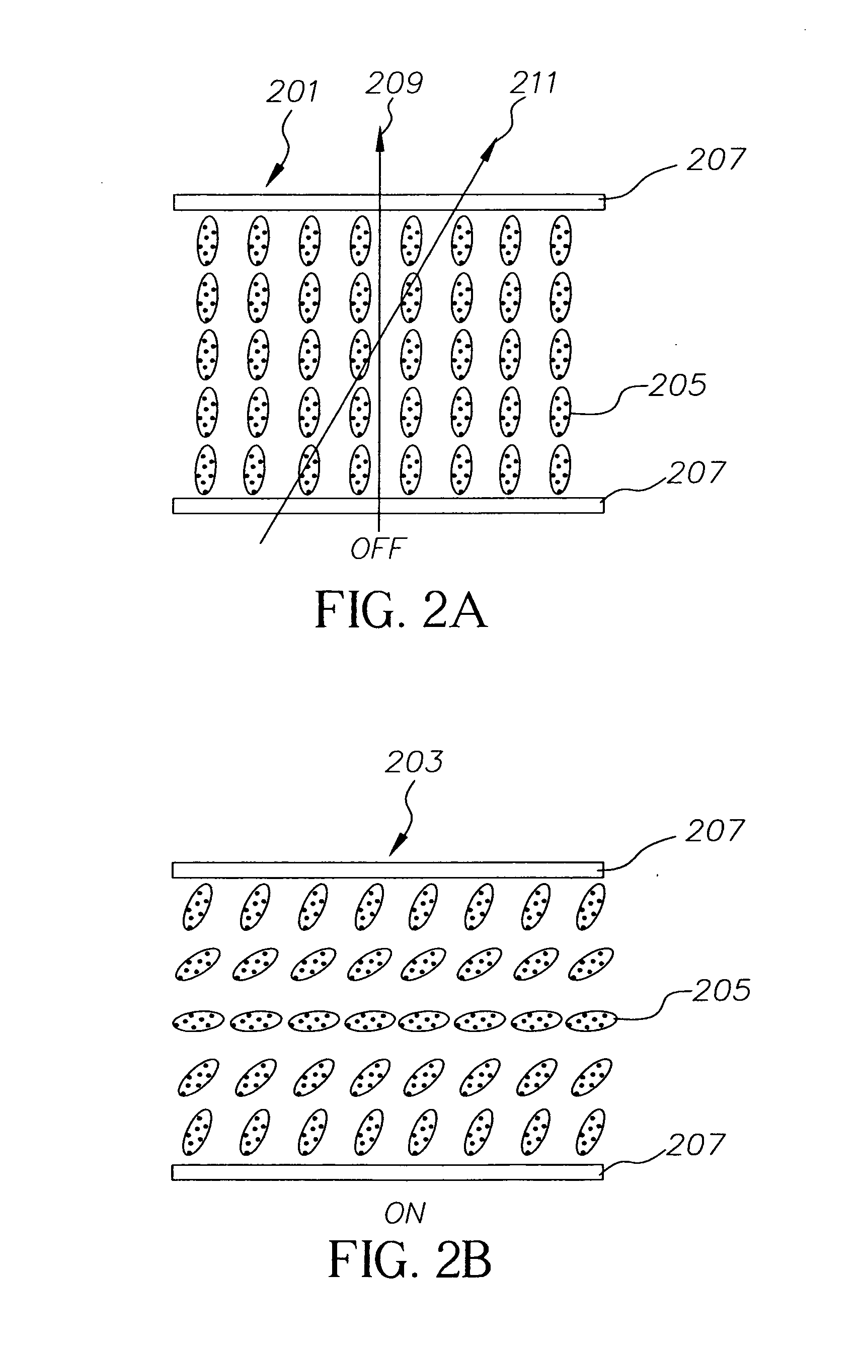
[0024] ON and OFF state refers to the state with and without applied voltage to the liquid crystal cell.

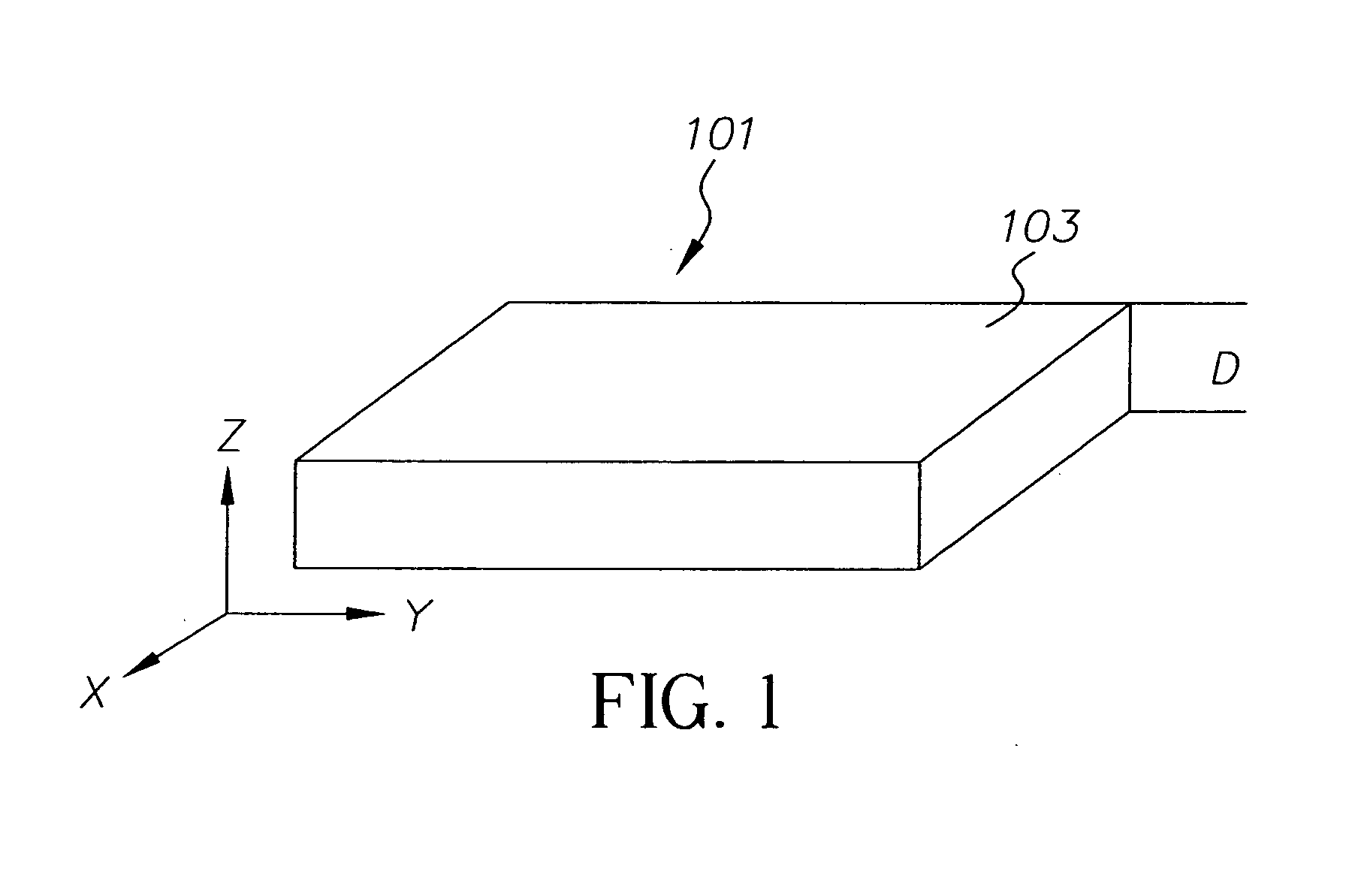
[0025] In-plane retardation, Rin, of a layer 101 shown in FIG. 1 is a quantity defined by (nx-ny)d, where nx and ny are indices of refraction in the direction of x and y. The x axis is taken as a direction of maximum index of refraction in the x-y plane and the y direction is perpendicular to the x axis. Thus Rin will always be a positive quantity. The x-y plane is parallel to the plane 103 of the layer. d is a thickness of the layer in the z-direction. The quantity (nx-ny) is referred to as in-plane birefringence, Δnin. It also will always have positive values. The values of Δnin and Rin hereafter are given at wavelength λ=550 nm.

[0026] Out of-plane retardation Rth of a layer 101 shown in FIG. 1, herein, is a quantity...


PUM

PropertyMeasurementUnit
Temperatureaaaaaaaaaa
Fractionaaaaaaaaaa
Timeaaaaaaaaaa

Abstract

A multilayer compensator includes one or more polymeric first layers and one or more polymeric second layers. The first layers comprise a polymer having an out-of-plane (Δnth) birefringence not more negative than −0.01 and not more positive than +0.01. The second layers comprise an amorphous polymer having an out-of-plane birefringence more negative than −0.01 or more positive than +0.01. An overall in-plane retardation (Rin) of the multilayer compensator is greater than 20 nm and the out-of-plane retardation (Rth) of the multilayer compensator is more negative than −20 nm or more positive than +20 nm. The in-plane retardation (Rin) of the one or more first layers is 30% or less of the overall in-plane retardation (Rin) of the multilayer compensator.

Description

CROSS-REFERENCE TO RELATED APPLICATIONS [0001] This is a Continuation-In-Part of U.S. non-provisional application Ser. No. 10 / 859,670, filed Jun. 3, 2004, (attorney docket number 86826), the entire contents of which are incorporated herein by reference.FIELD OF THE INVENTION [0002] The present invention relates to a multilayer optical compensator for liquid crystal displays. The invention also relates to a process for making such a compensator and liquid crystal displays using the compensator. BACKGROUND OF THE INVENTION [0003] Liquid crystals are widely used for electronic displays. In these display systems, a liquid crystal cell is typically situated between a pair of polarizer and analyzers. An incident light polarized by the polarizer passes through a liquid crystal cell and is affected by the molecular orientation of the liquid crystal, which can be altered by the application of a voltage across the cell. The altered light goes into the analyzer. By employing this principle, th...

Claims


Application Information

Patent Timeline
IPC IPC(8): C08G69/26G02B5/30G02F1/13363
CPCG02B5/3016Y10T428/1036Y10T428/10G02F1/133634C09K2323/00C09K2323/03G02B5/30G02F1/13363
Inventor ELMAN, JAMES F.GAMBLE, WILLIAM J.HURLEY, DANIEL F.
Owner NITTO DENKO CORP
Why Eureka
Try Eureka