Universal digital framer architecture for transport of client signals of any client payload and format type

a client signal and framer technology, applied in the field of digital communication system, can solve the problems of adding system costs (cogs) and no means for achieving the transport of each and every client signal, and achieve the effect of reducing system costs and reducing the required size or capacity

Active Publication Date: 2005-12-29
INFINERA CORP
View PDF38 Cites 127 Cited by
  • Summary
  • Abstract
  • Description
  • Claims
  • Application Information

AI Technical Summary

Benefits of technology

[0031] A further feature disclosed is the distributed format of the forward error correction (FEC) coding along the client signal frame payload in each row of the payload data frame thereby reducing the required size or capacity of a circular buffer in the logic circuitry to permit the conversion of client signal payload from a first time domain into a second time domain and vice versa.
[0032] Thus, in summary, the approach here permits the deployment of free running clocks in subsystem circuitry at an intermediate or terminal node element rather than utilizing PLL circuitry employing crystal oscillators, which are a necessity for synchronous clock operation required in the OTN and the present G.709 protocol, thereby reducing system costs. Also, by using local clocks, all signal jitt...

Problems solved by technology

This results in added system costs (COGS) because it is necessary, for example, to provide accurate clocking at each node in order to “recapture” the clock of the original transmitter node.
Accurate clocking entails the utilization of high cost, phase locked loop (PLL) circuitry and an expense crystal oscillator together with other required system components.
In...

Method used


Image

  • Universal digital framer architecture for transport of client signals of any client payload and format type
  • Universal digital framer architecture for transport of client signals of any client payload and format type
  • Universal digital framer architecture for transport of client signals of any client payload and format type

Examples


Embodiment Construction

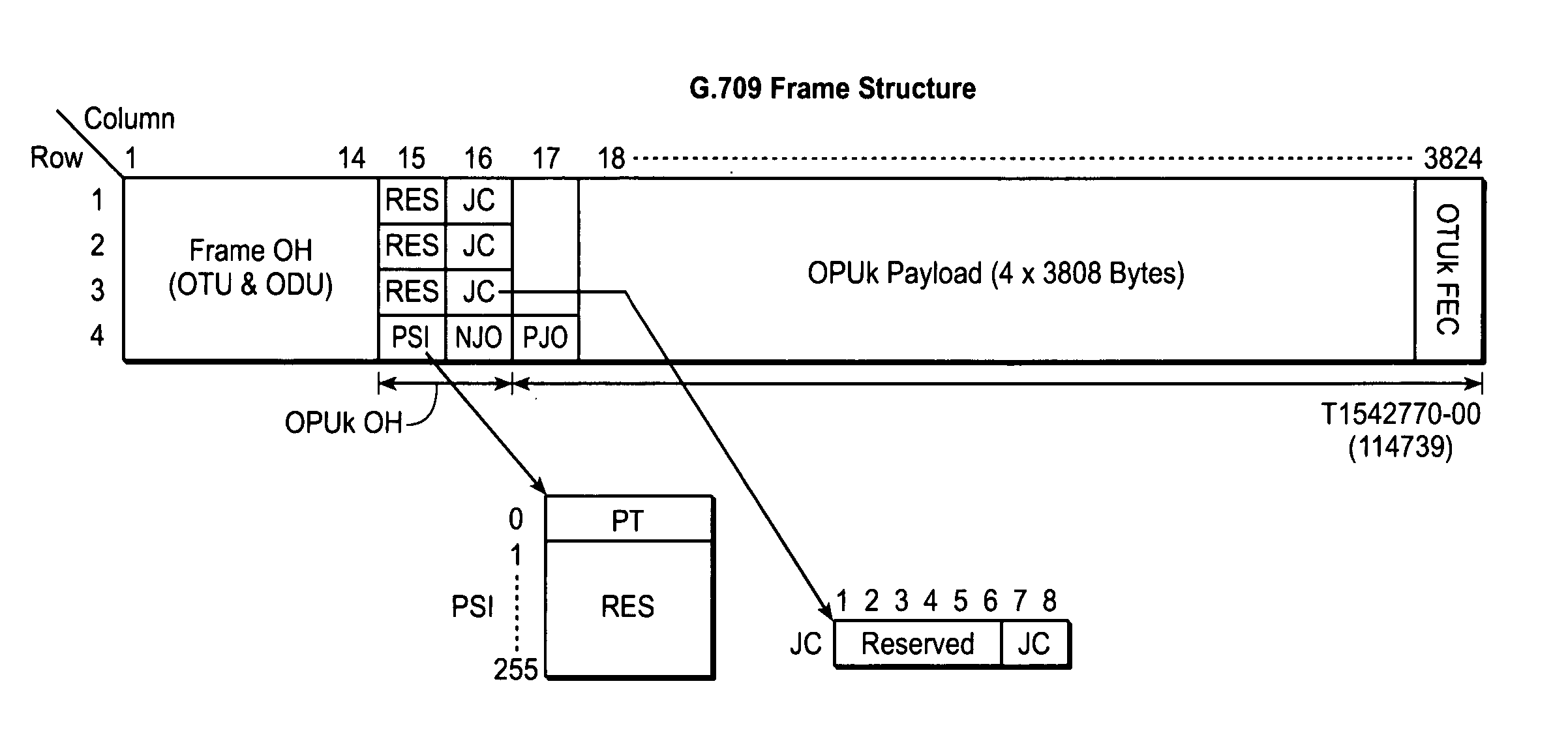
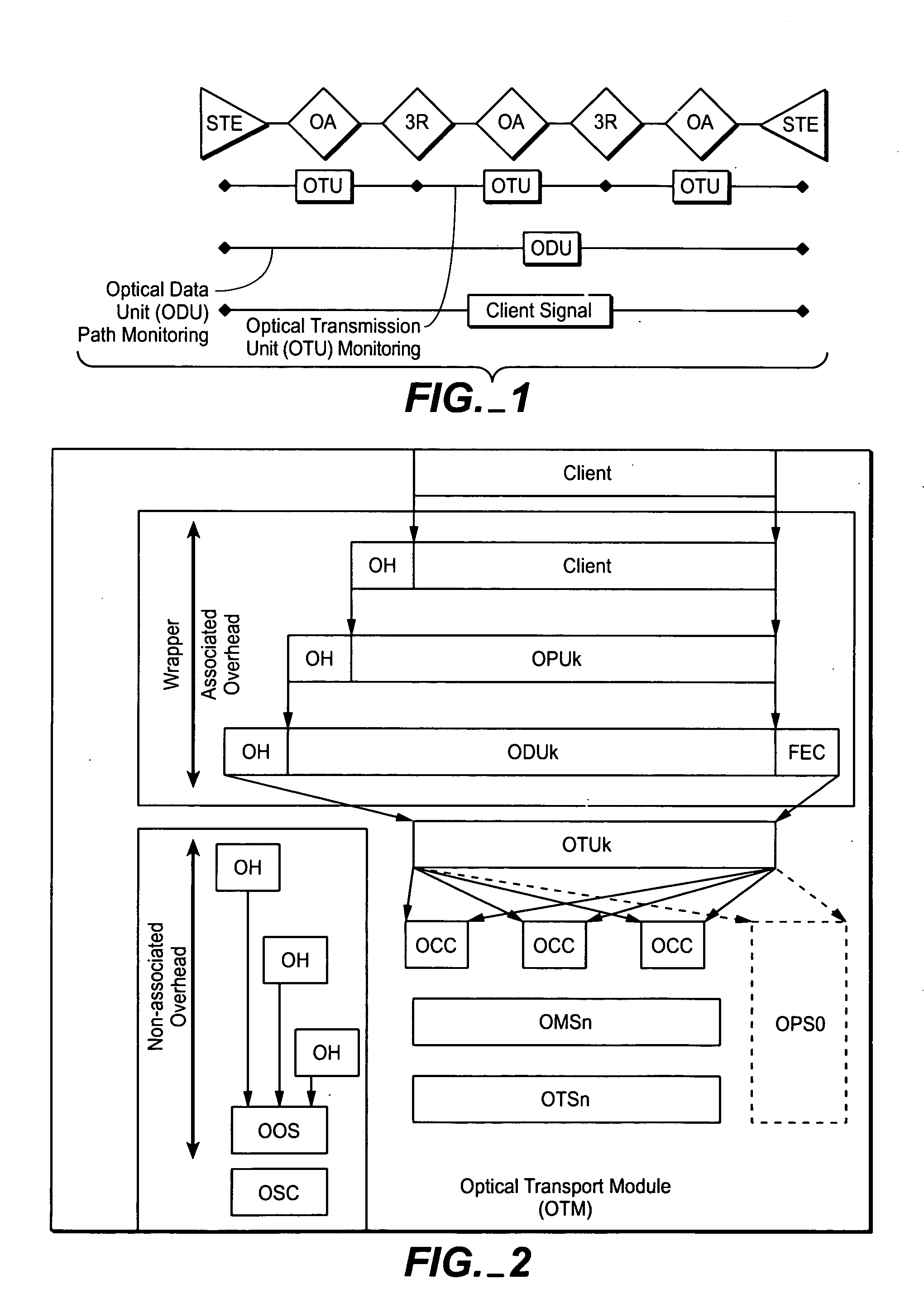
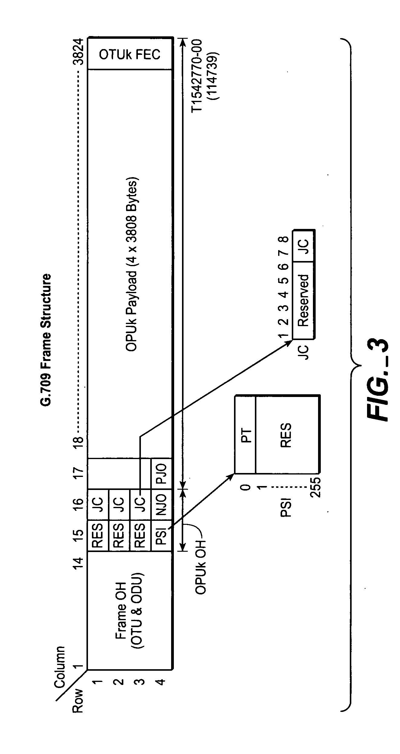
[0064] The digital optical network disclosed here is inherently asynchronous, and makes extensive use of OEO conversions at intermediate nodes, such as, signal regeneration nodes in the network, to provide “3R” functionality, i.e., any electronic signal reconditioning to correct for transmission impairments as well as 3R processing, such as, for example, but not limited to, FEC encoding, decoding and re-encoding, in addition to signal re-amplification (1R), signal reshaping (2R) and signal retiming (3R). See U.S. patent application Ser. No. 10 / 267,212, supra. In both of these respects (i.e., asynchronous operation and signal reconditioning), this network architecture partially runs counter to key architectural principles embodied in the ITU-T OTN architecture in general, and to the G.709 standard layering hierarchy in particular. In order to understand the application of this invention, it is important to understand digital wrapping as set forth in the current proposed draft for the...


PUM


Abstract

Client signals to be transported in a transmission network, particularly an optical transmission network, may have different payload envelope rates and are digitally mapped on the client egress side into first transport frames (also referred to as iDTF frames, or intra-node or internal digital transport frames), at the client side for intra-transport within terminal network elements (NEs) and further digitally mapped into second transport frames (also referred to as DTFs or digital transport frames) for inter-transport across the network or a link which, through byte stuffing carried out in the first transport frames so that they always have the same frame size. As a result, the system of framers provides for a DTF format to always have a uniformly universal frame rate throughout the network supporting any client signal frequency, whether a standard client payload or a proprietary client payload, as long as its rate is below payload envelope rate of the client signal. At the client signal ingress side, the signal are digitally demapped from the second transport frames (DTF format) into the first transport frames where the stuff bytes are removed and accordingly processed at an intermediate node element before further transport, or digitally demapped from the first transport frames (iDTF format) to reproduce or reassemble the client signal or signals comprising the client payload at the client payload envelope rate for reception at the client's equipment. Among various features disclosed, two predominate features are (1) a single channel or network rate for transport of all signals between network elements (NEs) and end terminal network elements and (2) the digitally wrapping of different types of payloads into N client side or first frames using stuff bytes to render each client side frame size equal to a predetermined value. Then the stuffed first frames are wrapped into line side or second frames for transport over the network at the same high speed line rate for all digitally wrapped client signals. The client side framers may be, for example, running at the lowest signal rate encountered, to digitally wrap then into parallel N client signals or digitally wrap a client signal multi-sected into N parts, where these two different client signals have different payload rates.

Description

REFERENCE TO RELATED APPLICATIONS [0001] This application claims priority to provisional patent application Ser. No. 60 / 580,240, filed Jun. 16, 2004 and, further, is a continuation-in-part of, and claims priority to, prior U.S. provisional patent application Ser. No. 60 / 427,159, filed Nov. 18, 2002, which is now U.S. nonprovisional patent application Ser. No. 10 / 715,947, filed Nov. 18, 2003, entitled OPTICAL TRANSMISSION NETWORK WITH ASYNCHRONOUS MAPPING AND DEMAPPING AND DIGITAL WRAPPER FRAM FOR THE SAME; which is a continuation-in-part of, and claims priority to, prior U.S. provisional patent application Ser. No. 60 / 392,494, filed Jun. 28, 2002, which is now U.S. nonprovisional patent application Ser. No. 10 / 267,212, filed Oct. 8, 2002, entitled DIGITAL OPTICAL NETWORK ARCHITECTURE and published on May 29, 2003 as Publication No. U.S.2003 / 0099018A1, all of which foregoing mentioned provisional and nonprovisional patent applications are incorporated herein in their entirety by thei...

Claims


Application Information

Patent Timeline
IPC IPC(8): H04J3/08H04J3/14H04J3/16H04L12/28H04L12/56
CPCH04J3/08H04J3/1611H04J3/14H04J3/1652
Inventor CHIANG, TING-KUANGPERKINS, DREW D.SPRAGUE, EDWARD E.MURPHY, DANIEL P.
Owner INFINERA CORP
Why Eureka
Try Eureka