Inlaid polishing pad and method of producing the same

a polishing pad and polishing technology, applied in the direction of manufacturing tools, grinding devices, lapping machines, etc., can solve the problems of increasing the difficulty of pattern transfer from a photomask to a photoresist layer, the cmp process suffers from low throughput, and the exposed pattern of the photoresist layer becomes increasingly distorted

Active Publication Date: 2005-12-29
IV TECH CO LTD
View PDF23 Cites 0 Cited by
  • Summary
  • Abstract
  • Description
  • Claims
  • Application Information

AI Technical Summary

Benefits of technology

[0011] In one aspect, the present invention provides an inlaid polishing pad having desired rigidity and compressibility to meet the requirements of polishing planarity and uniformity.

Problems solved by technology

Limited by the focus depth of an exposing machine, pattern transferal from a photomask to a photoresist layer becomes increasingly difficult, and the exposed pattern of the photoresist layer becomes increasingly distorted.
The CMP process thus suffers from low throughput.
As stated in U.S. Pat. No. 6,217,426, although a composite polishing pad can partially satisfy both the planarity and the uniformity requirements of the CMP process, some new problems are introduced.
For example, pressure transmission is different for a rigid pad and a soft pad, and the polishing uniformity can sometimes be poor.
Furthermore, the more layers that are stacked in a composite polishing pad, the more variable the rigidity and compressibility become and thus the more difficult to control are the polishing planarity and uniformity.
Besides, if the two pads in a composite polishing pad are not adhered together well enough, the composite polishing pad may easily delaminate during the polishing process.
In the prior art described above, the cost and complexity in producing a polishing pad are unavoidably increased.

Method used


Image

  • Inlaid polishing pad and method of producing the same
  • Inlaid polishing pad and method of producing the same
  • Inlaid polishing pad and method of producing the same

Examples


embodiment 1

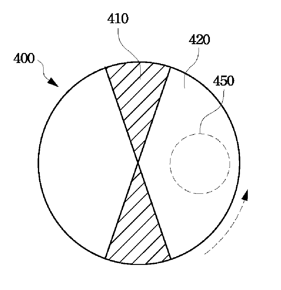
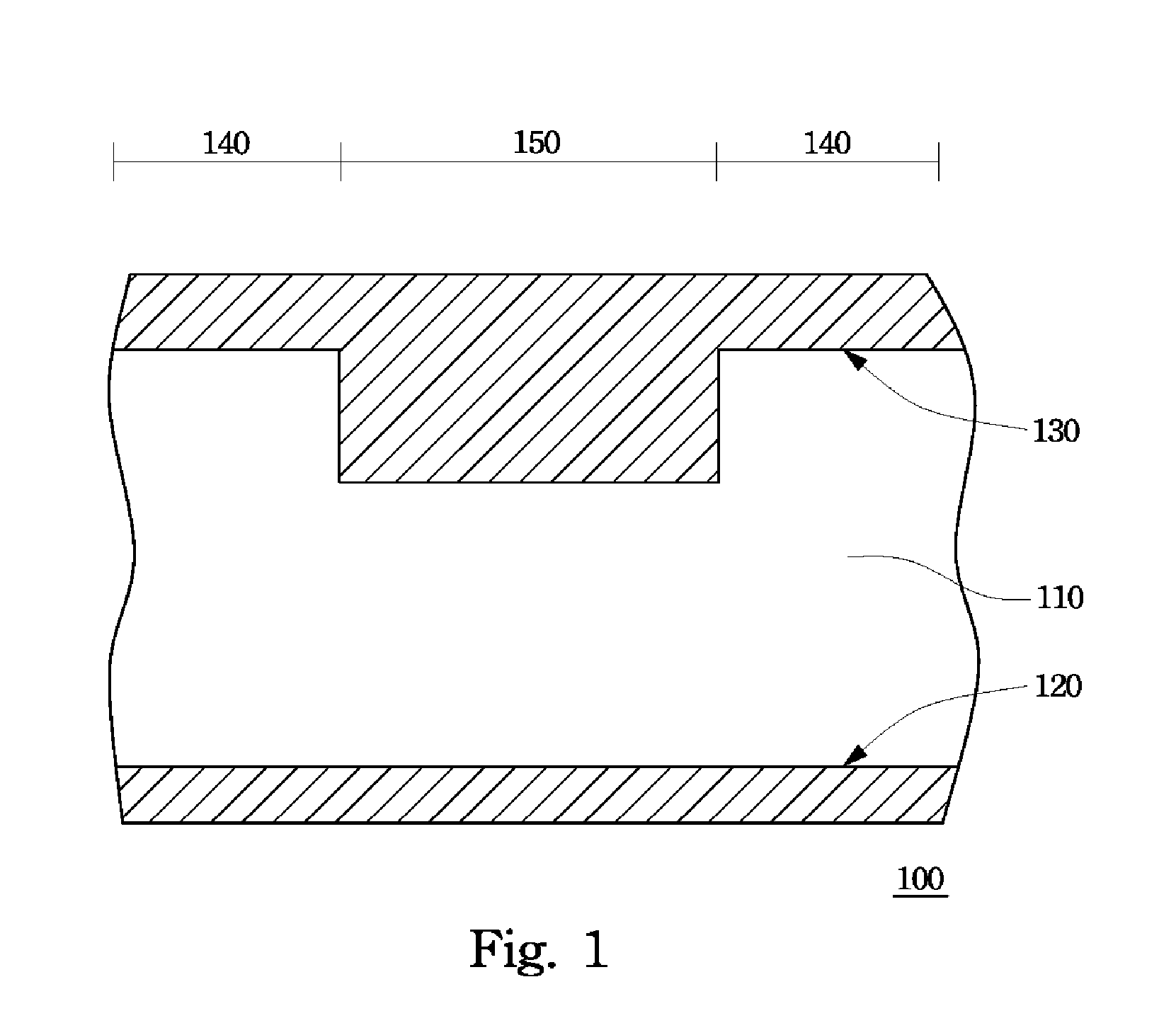
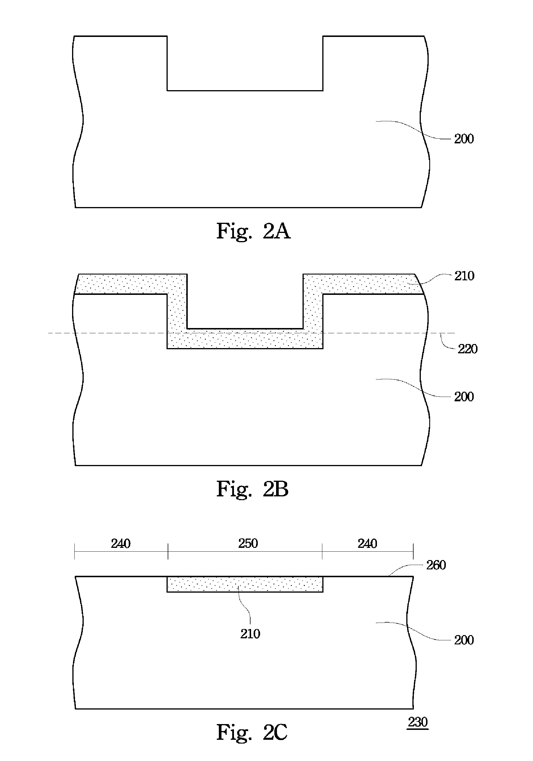
[0032]FIGS. 2A-2C are schematic, cross-sectional views showing a process of producing polishing pads according to a preferred embodiment of this invention. First, a polymer is molded in a cavity 110 of the mold 100 in FIG. 1 to form a semi-finished pad 200 with thicker and thinner regions, shown in FIG. 2A. In FIG. 2B, a surface treatment is performed on the top surface of the semi-finished pad 200 to form a treated layer 210 having different rigidity on the top portion of the semi-finished pad 200. The semi-finished pad 200 can be leveled along the line 220 shown in FIG. 2B to form a polishing pad 230, as shown in FIG. 2C. In FIG. 2C, the top surface 260 of the polishing pad 230 has at least two regions with different rigidities; that is, the region 240 and the region 250. The region 250 is formed by the treated layer 210 inlaid in the top surface 260.

[0033] According to a preferred embodiment, the surface treatment in the process of producing the polishing pad 230 can be illumina...

embodiment 2

[0038]FIGS. 3A and 3B are schematic, cross-sectional views showing a process of producing polishing pads according to another preferred embodiment of this invention. With reference to FIGS. 1, 3A and 3B, first, a small amount of first polymer is formed in the cavity 110 of the mold 100 to form a surface layer 310, wherein the first polymer does not fully fill the cavity 110. The forming method of the first polymer includes injection molding or in-mold coating. Then, a second polymer is injected into the cavity 110 of the mold 100 to fully fill the volume surrounded by the surface layer 310, as shown in FIG. 3A.

[0039] The surface layer 310 and the body 320, formed by the method of the two-step injection molding, compose the semi-finished pad 300 with thinner and thicker regions in FIG. 3A. The semi-finished pad 300 is then leveled along the line 330 shown in FIG. 3A to form a polishing pad 360, as shown in FIG. 3B. In FIG. 3B, the top surface 370 of the polishing pad 360 has at leas...


PUM

PropertyMeasurementUnit
rigidityaaaaaaaaaa
densitiesaaaaaaaaaa
shapeaaaaaaaaaa

Abstract

A surface treatment or a two-step injection molding is used to make an inlaid polishing pad. A surface of the inlaid polishing pad has areas of different rigidity to control the rigidity and compressibility of the inlaid polishing pad. Furthermore, methods of making such an inlaid polishing pads are also disclosed.

Description

CROSS-REFERENCE TO RELATED APPLICATION [0001] This application claims the priority benefit of U.S. Provisional Application Ser. No. 60 / 521,740, filed Jun. 29, 2004, the full disclosures of which are incorporated herein by reference.BACKGROUND OF THE INVENTION [0002] 1. Field of Invention [0003] The present invention relates to a polishing apparatus and manufacturing method thereof. More particularly, the present invention relates to an inlaid polishing pad and a method of producing the same. [0004] 2. Description of Related Art [0005] During the manufacturing process of semiconductor integrated circuits, isolation structures, metal lines and dielectric layers are stacked layer by layer, causing the surface of a wafer to become less and less planar. Limited by the focus depth of an exposing machine, pattern transferal from a photomask to a photoresist layer becomes increasingly difficult, and the exposed pattern of the photoresist layer becomes increasingly distorted. Chemical mechan...

Claims


Application Information

Patent Timeline
Patent Type & Authority Applications(United States)
IPC IPC(8): B24B1/00B24B37/04B24B37/20B24D13/14B24D18/00
CPCB24B37/22B24D18/00B24B37/24
Inventor SHIH, WEN-CHANG
Owner IV TECH CO LTD
Why Eureka
Try Eureka