Method of gastrostomy, and an infection preventive cover, kit or catheter kit, and a gastrostomy catheter kit

a technology of infection prevention and catheter kit, which is applied in the field of gastrostomy, can solve the problems increased risk of infection of the wounded part of the patient, and increased risk of infection of the upper pharynx or esophagus, so as to reduce the the effect of shortened time required for gastrostomy

Inactive Publication Date: 2005-12-29
SUZUKI CO LTD Y
View PDF45 Cites 11 Cited by
  • Summary
  • Abstract
  • Description
  • Claims
  • Application Information

AI Technical Summary

Benefits of technology

[0054] There are following merits in using the above PEG catheter of the present invention. When the guide wire which is pulled through an esophagus and an oral cavity into a space outside the patient is joined with the top portion of the PEG catheter in the method of gastrostomy, the operator has only to insert the top end (head) of the guide wire into the opening formed on the conical top portion. The head formed on the top end of the guide wire enters into the hollow inside of the top portion through the top opening. The guide wire and the head are prevented from being pulled out by the engaging piece. Thus the guide wire is joined with the conical top portion of the PEG catheter. Accordingly, work for joining the guide wire with the PEG catheter is easy and time required for gastrostomy is shortened. In one embodiment, the engaging piece is disposed inside of the conical hollow top portion obliquely with respect to an axial direction of the conical hollow top portion, and the engaging piece is formed with a first slit for passing having a width larger than the head of the guide wire at an end portion of the piece which is directed to the guide wire insertion direction and a second slit for pull-out prevention having a width smaller than the head of the guide wire and being coupled with the first slit.
[0055] As described above, the first wide slit for passing which is formed on the engaging piece provided in hollow inside of the conical top portion of the PEG catheter allows the head formed on the top end of the guide wire to pass therethrough. When the guide wire is inserted into the hollow inside of the conical top portion through the top opening, the inserted head of the guide wire proceeds to through the first slit of the engaging piece (beyond the engaging piece). The guide wire portion (exclusive of the head) enters (falls down) into the narrow slit for pull-out prevention which is connected to or coupled with the wide first slit. Since the second slit is narrower than the top head of the guide wire in width, the top head is prevented from being pulled out (moving) even if the guide wire is pulled toward outside. The guide wire and the PEG catheter can be easily joined or linked and time required for gastrostomy is shortened.

Problems solved by technology

However, these methods include the drawbacks described below.
The endoscope is required to be twice inserted in the pertinent patient, which leads to a problem of complex operations and pain to patients.
There exists a fear of damage to the larynx, the upper pharynx or the esophagus.
The PEG catheter (including a PEG tube and a dome connected to the tube) is infected in the oral cavity, the upper pharynx or the larynx and hence the wounded part of the patient is liable to be infected.
However, the second drawback, i.e., the infection of the wound due to the contamination of the PEG tube and the dome has a high possibility of occupancy.
This resultantly delays the starting point of the enteral feeding for the patient, and the immunity of the patient from diseases is weakened, this may lengthen the hospital treatment in some cases.
The patient suffers from serious pains and the fee for medical treatment soars.
Consequently, not only the patient but also family members of the patient must bear the expense and suffer from mental stress.
However, this is not the basic countermeasure.

Method used


Image

  • Method of gastrostomy, and an infection preventive cover, kit or catheter kit, and a gastrostomy catheter kit
  • Method of gastrostomy, and an infection preventive cover, kit or catheter kit, and a gastrostomy catheter kit
  • Method of gastrostomy, and an infection preventive cover, kit or catheter kit, and a gastrostomy catheter kit

Examples


first embodiment

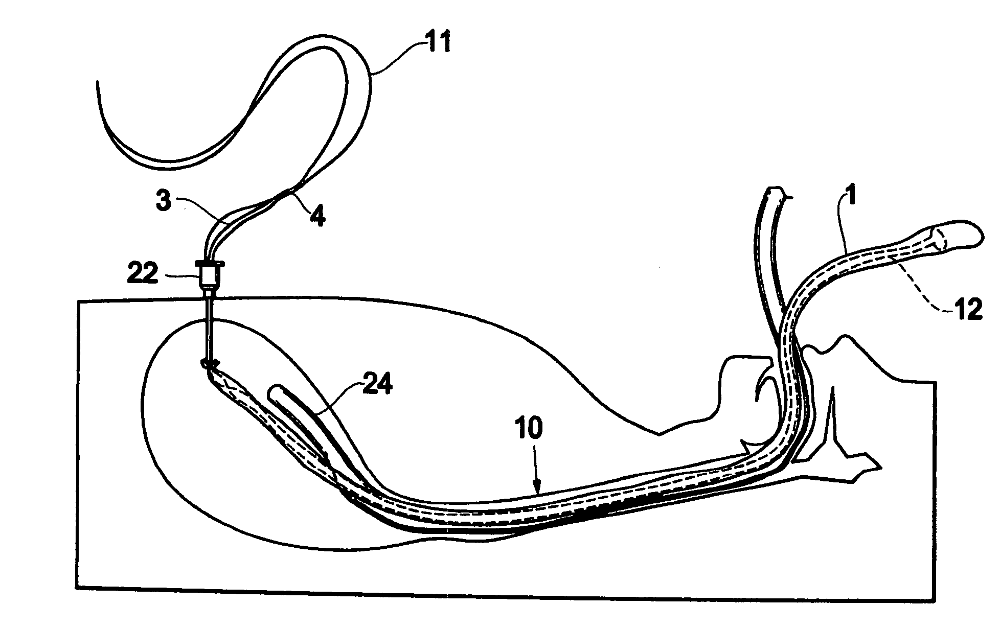
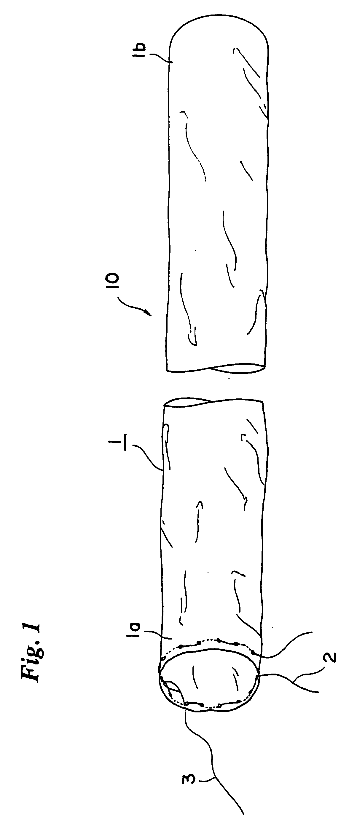
[0097]FIG. 1 shows an infection preventive cover of the first embodiment used in a percutaneous endoscopic gastrostomy (PEG).

[0098] The infection preventive cover 10 includes an elongated sheath 1 having at least one end 1a opened. The sheath 1 includes another end 1b, which may be closed, opened, or provided with a hole. The sheath 1 has a length greater than that of a gastrostomy catheter (referred to as “a PEG catheter”) 12, which will be described later. The diameter of the sheath 1 is substantially equal to, or greater than that of a dome 13 connected to an end edge of the catheter 12. When the sheath 1 is made of a elastic or expansive material, the diameter thereof may be slightly smaller than that of the dome 13. In either case, it is only required that the PEG catheter 12 including the dome 13 passes through the sheath 1. It is desirable that a lubricant such as a lubricant jerry is applied on an inner surface of the sheath 1.

[0099] The sheath 1 is manufactured with a thi...

second embodiment

[0148]FIG. 23 shows an infection preventive cover 10F of the second embodiment used in a percutaneous endoscopic gastrostomy (PEG). FIG. 24 shows a top end portion of the infection preventive cover 10F in an enlarged form. In these drawings, the same reference numerals are assigned to the same elements as those shown in FIGS. 1 and 16 in order to avoid overlapped explanation.

[0149] Preferably in the same way as shown in FIG. 16, the circumferential periphery portion 1C of the opening end 1a of the sheath 1 is folded back outside and the folded-back portion 1C is melted (or welded or adhered) at its edge to the sheath 1 (the adhered portion is indicated by a reference numeral 1D) to form a bag, a path or a guide along the edge of the opening end of the sheath 1. The circumferential periphery portion 1C of the opening end of the sheath may be folded back inside. A closing thread or string 6 is passed through the bag, path or guide. Both ends of the closing thread 6 are outwardly led ...


PUM


Abstract

A PEG catheter is prevented from being infected. An infection preventive cover includes an elongated sheath having one opening end. The opening end is embroidered with a ligature at its circumferential section. A guide wired which is inserted through an abdominal wall into a stomach and which is then drawn out of an oral cavity is linked with a joint wire of a PEG catheter. Thereafter, the PEG catheter is covered with the infection preventive cover. The opening end of the sheath is tied up by the ligature. By pulling the guide wire on the abdomen wall side, the PEG catheter covered with the cover is delivered into the stomach. By pulling a cutting wire exposed through the abdomen wall, the ligature is cut off and the opening end of the cover is opened. Further in order to make it easy to close tightly and to loose an opening end, another infection preventive cover is provided. A closing thread which is embroidered along a circumferential edge of the opening end of a sheath is apart from the embroidered portion and loosely passes through a tightening tube to be led outside from an outer end of the tube. when a portion of the thread which is led outside the tube is pulled out, the opening end of the sheath is closed by the closing thread. The thread is kept in its tightened state. When the tightened thread is loosened, the opening end of the sheath is naturally opened or becomes openable state.

Description

[0001] The present Application is a Divisional Application of U.S. patent Ser. No. 09 / 574,452 (CIP) filed on May 19, 2000, and entitled “A METHOD OF GASTROSTOMY, AND AN INFECTION PREVENTIVE COVER, KIT OR CATHETER KIT, AND A GASTROSTOMY CATHETER KIT”, by Yutaka Suzuki. [0002] The present invention is related to U.S. patent application Ser. No. 09 / 375,374, filed on Aug. 17, 1999, now abandoned and entitled “A METHOD OF GASTROSTOMY, AND AN INFECTION PREVENTIVE COVER AND A GASTROSTOMY CATHETER KIT” by Yutaka Suzuki.BACKGROUND OF THE INVENTION [0003] 1. Field of the Invention [0004] The present invention relates to a method of gastrostomy, and an infection preventive cover, kit or catheter kit and a gastrostomy catheter kit for use with the method. [0005] 2. Description of the Related Art [0006] For a percutaneous endoscopic gastrostomy (PEG) enabling enteral feeding of a patient who finds swallowing food difficulty or who cannot swallow, it is sufficient to apply a local anethesia to th...

Claims


Application Information

Patent Timeline
Patent Type & Authority Applications(United States)
IPC IPC(8): A61B17/00A61B17/34A61B19/00A61B19/08A61J15/00A61M25/01A61M31/00
CPCA61B17/3415A61B19/08A61B19/38A61B2017/00287Y10S128/24A61J15/0019A61J15/0023A61J15/0034A61M25/0111A61B2019/083A61B46/17A61B46/00A61B90/40
Inventor SUZUKI, YUTAKA
Owner SUZUKI CO LTD Y
Why Eureka
Try Eureka