
Micro integrated cardiac pacemaker and distributed cardiac pacing system

a distributed cardiac and pacemaker technology, applied in television systems, artificial respiration, therapy, etc., can solve problems such as defective pacing, lead wire breakage, and conventional pacemakers, and achieve the effect of suppressing the detection of intracardiac p wave information

Active Publication Date: 2005-12-29
FUJIKIN INC +1
View PDF5 Cites 61 Cited by
  • Summary
  • Abstract
  • Description
  • Claims
  • Application Information

AI Technical Summary

Benefits of technology

[0039] The first ultra miniature integrated cardiac pacemaker is equipped with a control unit that outputs control signals, a power unit that supplies the driving power, a heart stimulating means that responds to the control signal and electrically stimulates the atrial myocardium, an electrocardiographic information detecting means that detects the electrocardiographic information including at least intracardiac P wave information, a transmitting means that modulates the electrocardiographic information and sends the information to the second ultra miniature integrated cardiac pacemaker, and a receiving means that receives and demodulates the electrocardiographic information sent from the second ultra miniature integrated cardiac pacemaker.

Problems solved by technology

However, conventional pacemakers have the following problems.
Since the main body of the cardiac pacemaker and the electrodes are connected by lead wires, cases of breaking of the lead wires have occurred.
Breakage of the lead wires results in defective pacing.
In addition, there have been also cases of venous obstruction by the lead wires.
Moreover, during the early stages after implantation of the cardiac pacemaker, a shift in position of the electrodes may cause defective pacing.
When a shift in position of the electrodes occurs, a second operation has to be performed, which adds extra strain for the patient.
Furthermore, if there is a defective hermetic sealing structure at the junction between the cardiac pacemaker main body and the lead wires, this may lead to defective pacemaker movement.
Problems with electrical safety have also occurred.
However, even for this type of cardiac pacemaker, surgical implantation of the pacemaker cannot be avoided, and there have been cases in which skin necrosis occurred at the cardiac pacemaker implantation site.

Method used


Image

  • Micro integrated cardiac pacemaker and distributed cardiac pacing system
  • Micro integrated cardiac pacemaker and distributed cardiac pacing system
  • Micro integrated cardiac pacemaker and distributed cardiac pacing system

Examples


first embodiment

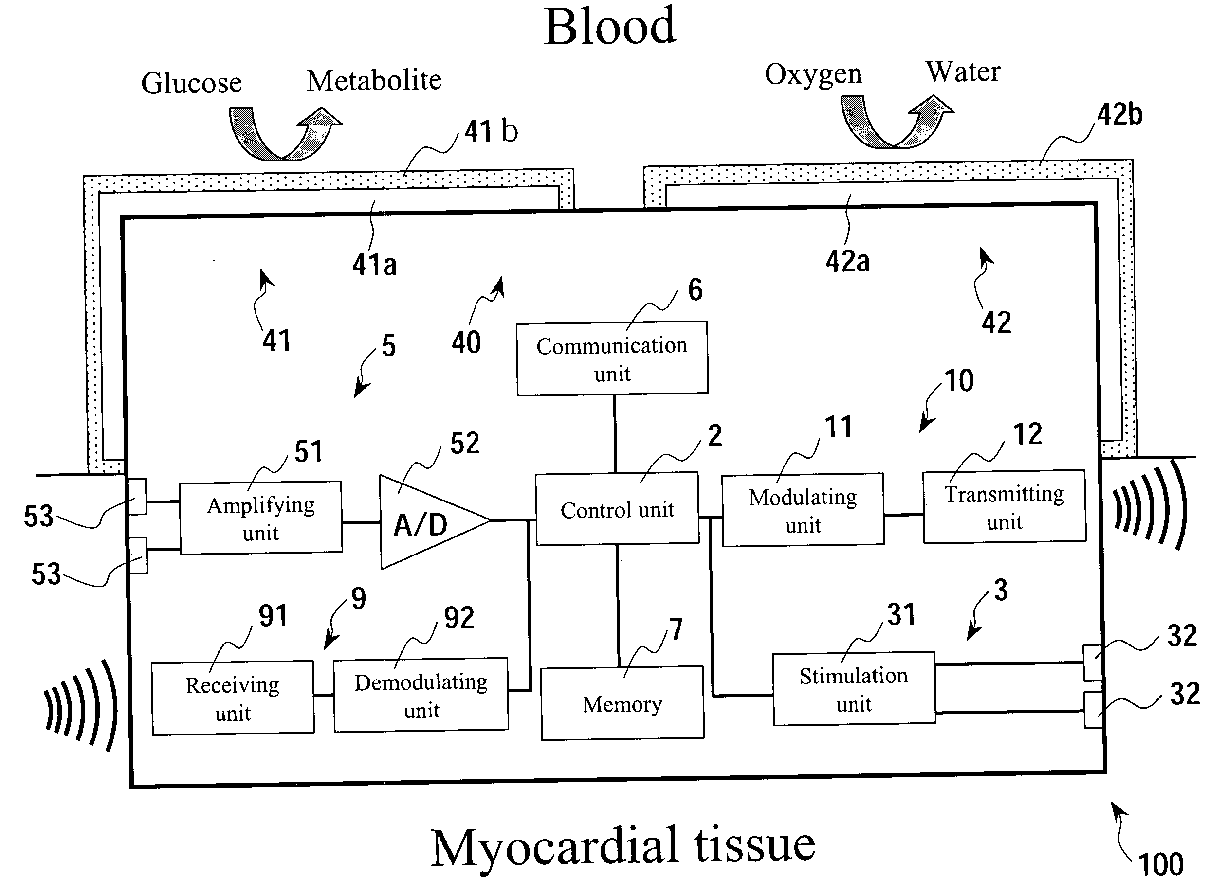
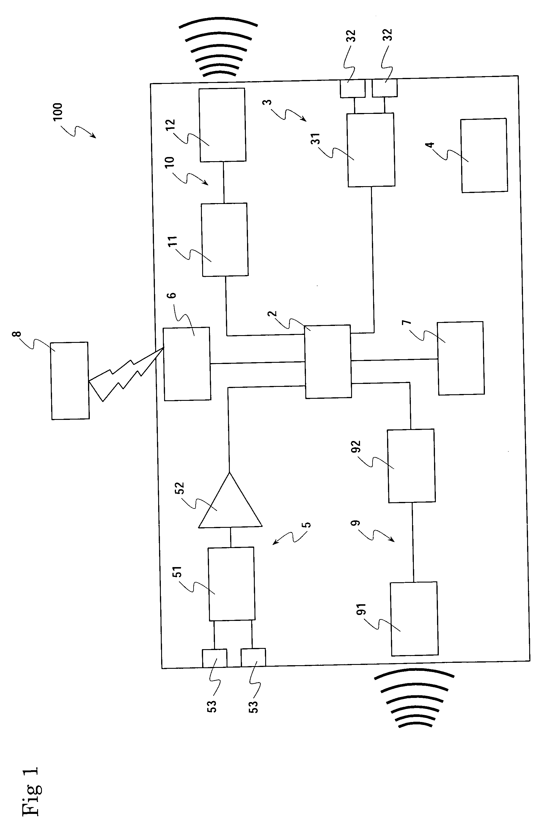
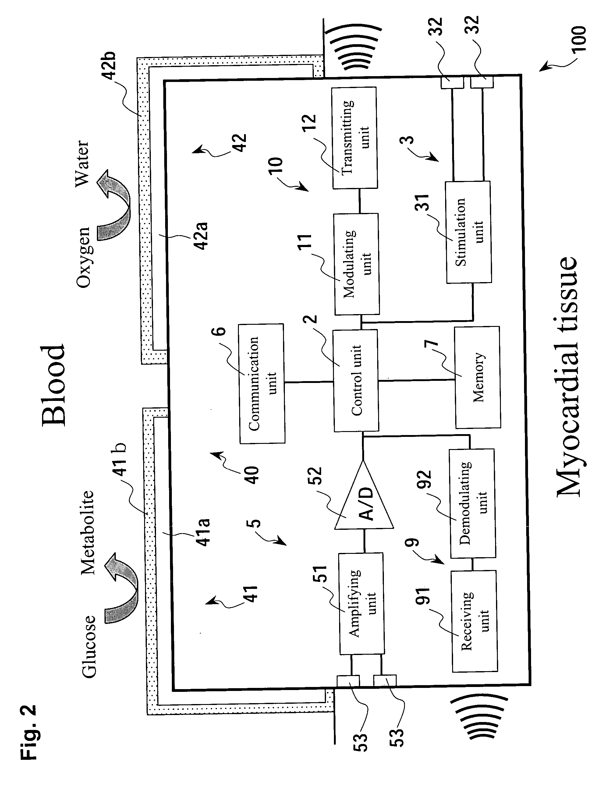
[0075] The present invention is described in detail below while referring to the figures. FIG. 1 is a simplified block diagram of an ultra miniature integrated cardiac pacemaker (100) in accordance with this invention.

[0076] The ultra miniature integrated cardiac pacemaker (100) in this embodiment is composed of a control unit (2) that outputs control signals, a heart stimulating means (3) that responds to the control signals and electrically stimulates the heart tissue, an electrocardiographic information detecting means (5) that detects the electrocardiographic information and outputs it to the control unit (2), a transmitting means (10) that modulates the control signals output from the control unit (2) and / or electrocardiographic information detected by the electrocardiographic information detecting means (5) and sends the information outside, a receiving means (9) that receives and demodulates the information sent from outside, and a power unit (4) that supplies the driving cur...

third embodiment

[0170] In the distributed cardiac pacing system, it is possible to place an ultra miniature integrated cardiac pacemaker (101), instead of the electrocardiographic information detecting device (200), in the atrial endocardium just like the above-mentioned distributed cardiac pacing system in the previous embodiment. As described in the distributed cardiac pacing system in the previous embodiment (i.e., the distributed cardiac pacing system), the ultra miniature integrated cardiac pacemaker placed in the atrial endocardium is equipped with a stimulation timing determining means and stimulation timing changing means, and therefore may be used in patients with lowered ventricular contractility accompanying sinus arrest and atrioventricular block, as well as in patients with a risk of fatal arrhythmia accompanying sinus arrest and atrioventricular block.

[0171] In the distributed cardiac pacing system of this revised embodiment, for the design of the ultra miniature integrated cardiac pa...


PUM

PropertyMeasurementUnit
diameteraaaaaaaaaa
timeaaaaaaaaaa
currentaaaaaaaaaa

Abstract

A micro integrated cardiac pacemaker includes a control unit for outputting a control signal according to cardiograph information, heart stimulating means for stimulating heart tissue in response to the control signal, cardiograph information extracting means for extracting cardiograph information and outputting it to the control unit, and a power supply unit for supplying drive power. The power supply unit is a biological fuel cell that takes out electrons by oxidation of a biological fuel. The biological fuel cell includes an anode and a cathode. An oxidase of a biological fuel and a mediator are immobilized on the cathode. Blood and / or body fluid are used as an electrolytic solution, and a biological fuel and oxygen in the blood and / or the fluid are used. The biological fuel cell is attached to the end of a catheter and implanted into the heart, and the catheter is withdrawn, without incising the breast.

Description

BACKGROUND OF THE INVENTION [0001] 1. Field of the Invention [0002] The present invention concerns an ultra miniature integrated cardiac pacemaker and distributed cardiac pacing system. The invention provides an ultra miniature integrated cardiac pacemaker and distributed cardiac pacing system that allows pacing of the heart without the need for conventional lead wires that connect the electrodes and the main body of the pacemaker, and allows implantation by catheter manipulation without incising the chest wall, which avoids imposing an extra burden on the user. [0003] In this invention, “ultra miniature” refers to the minute size of the pacemaker to the extent that it can be attached to the tip of a catheter. [0004] 2. Description of Related Art [0005] A cardiac pacemaker is a device that controls the rhythm of the heart by delivering electrical impulses to the heart, and is indicated for use in patients with symptoms of bradyarrhythmia. [0006] A conventional cardiac pacemaker incl...

Claims


Application Information

Patent Timeline
Patent Type & Authority Applications(United States)
IPC IPC(8): A61B5/0402H04N5/44A61N1/32A61N1/36A61N1/362A61N1/365A61N1/368A61N1/37A61N1/372A61N1/375A61N1/378H01M8/16H04B1/16H04N5/00H04N7/025H04N7/03H04N7/035
CPCA61N1/368A61N1/37205A61N1/37288Y02E60/527A61N1/3785H01M8/16A61N1/3756Y02E60/50A61N1/36507
Inventor SUNAGAWA, KENJI
Owner FUJIKIN INC
Learn More