Method of installing a radiant density floor heating system

a technology of radiant density and floor heating, which is applied in heat-proofing, synthetic resin layered products, transportation and packaging, etc., can solve the problems of reducing the performance of radiantly heated slabs, reducing the reflectivity of foils, and not entirely effective materials currently used in the ar

Inactive Publication Date: 2006-01-05
SEALED AIR CORP
View PDF22 Cites 15 Cited by
  • Summary
  • Abstract
  • Description
  • Claims
  • Application Information

AI Technical Summary

Benefits of technology

[0008] Despite numerous attempts to provide an effective product that can be used to insulate under concrete slabs, the materials presently used in the art are not altogether effective. Although there is ample evidence that air cellular cushioning products work in insulating under concrete slabs, it has been further suggested that the performance is from the foil reflecting radiant energy. It has been found that this theory is incorrect as it is a well-known fact that coating the foil surface or applying a film to it will substantially reduce the reflectivity of the foil. Moreover, it has been found that the use of the conductive / insulation pad of this invention reduces or eliminates ground water intrusion into the concrete slab. Cold ground water will reduce the performance of a radiantly heated slab. Secondly, the aluminum foil does not act as a reflector as well as it does a conductor of heat allowing radiant energy to spread out under the slab improving performance.
[0009] In accordance with the present invention, there is provided a multi-layered conductive / insulation pad. In a first embodiment of the invention a multi-layer conductive / insulation pad is provided having, in order, a first polymer layer, a conductive layer, such as a thin foil of metal or a metallized thermoplastic film, laminated to the first polymer layer, a second polymer layer laminated to the side of the conductive layer opposite the side of the first polymer layer. At least one air cellular cushioning layer is laminated to the side of the second polymer film opposite the conductive layer. Optionally, a protective polymer layer is laminated to the first air cellular cushioning layer on the opposite side of the second polymer layer. The first and second polymer layers are laminated to the opposite sides of the conductive layer to protect the layer from oxidizing and to protect the layer from the lime in the curing concrete, and, when used directly on the soil, the alkali content in the soil. The insulation component (air cellular cushioning material) prevents the ground water intrusion into the concrete slab, as well as heat loss into the cold ground water. The conductive layer, i.e., foil or metallized film, conducts the heat throughout the layer allowing radiant energy to spread out under the slab.
[0010] For the product to be efficient, the conductive layer needs to be as close as possible to the concrete slab, without having any insulation between the slab and the conductive layer. An advantage of the pad of the present invention is that the air cellular cushioning layer insulation between the conductive layer and the concrete slab is eliminated which makes the conductive layer a more effective conductor of heat allowing radiant energy to spread out under the concrete slab.
[0014] Another object of the present invention is to provide a reflective layer that conducts heat throughout the layer allowing radiant energy to spread out under the slab and preventing dispersal of heat below the reflective surface.

Problems solved by technology

Despite numerous attempts to provide an effective product that can be used to insulate under concrete slabs, the materials presently used in the art are not altogether effective.
It has been found that this theory is incorrect as it is a well-known fact that coating the foil surface or applying a film to it will substantially reduce the reflectivity of the foil.
Cold ground water will reduce the performance of a radiantly heated slab.
Secondly, the aluminum foil does not act as a reflector as well as it does a conductor of heat allowing radiant energy to spread out under the slab improving performance.

Method used


Image

  • Method of installing a radiant density floor heating system
  • Method of installing a radiant density floor heating system

Examples


Embodiment Construction

[0023] The present inventions now will be described more fully hereinafter with reference to the accompanying drawings, in which some, but not all embodiments of the invention are shown. Indeed, these inventions may be embodied in many different forms and should not be construed as limited to the embodiments set forth herein; rather, these embodiments are provided so that this disclosure will satisfy applicable legal requirements. Like numbers refer to like elements throughout.

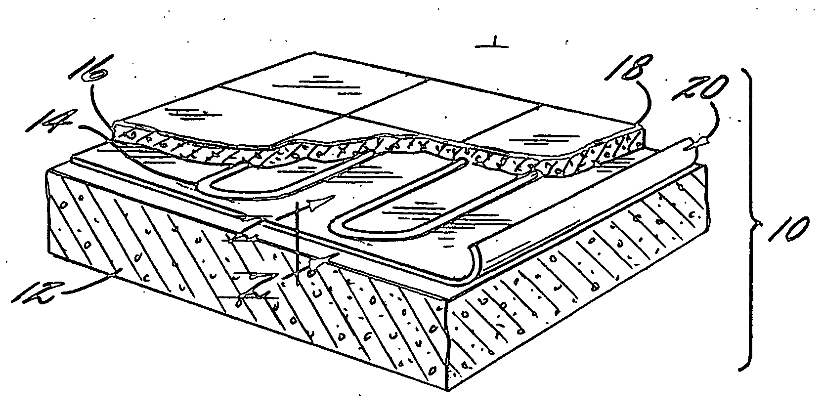
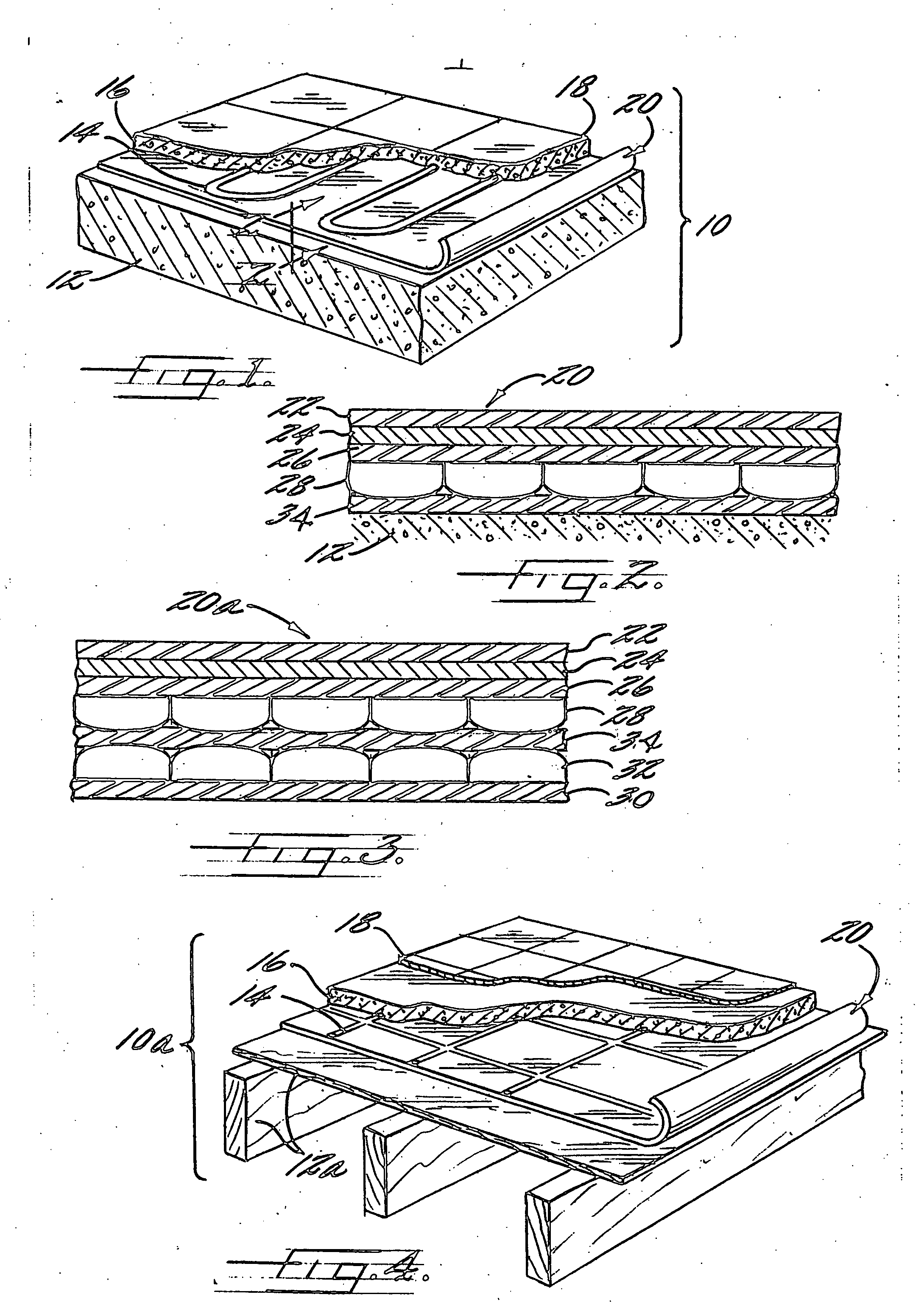
[0024] Referring more particularly to the drawings, there is shown in FIG. 1 a perspective view of a radiant heating assembly 10 showing a conductive / insulation pad 20 overlaying the ground 12. A heating element 14 is placed above the conductive / insulation pad 20 and positioned so that the heating element 14 may be surrounded by the slab 16. The slab 16 comprises a layer of concrete or other cementitious material and is poured so that it covers the conductive / insulation pad 20 and embeds the heating element 1...


PUM

PropertyMeasurementUnit
thicknessaaaaaaaaaa
thickaaaaaaaaaa
thickaaaaaaaaaa

Abstract

A method of installing a radiant density floor heating system, in which a multi-layer conductive / insulation pad is disposed atop the ground or a subfloor, a heating element is placed atop the pad, a concrete or cement layer is laid atop the heating element and pad, and a flooring material is laid atop the cement layer. The pad comprises a first polymer layer having a first side that forms an outer surface of the multi-layer conductive / insulation pad, a conductive layer laminated to an opposite second side of the first polymer layer, a second polymer layer laminated to the side of the conductive layer opposite the first polymer layer, and a first air cellular cushioning layer laminated to the side of the second polymer layer opposite the conductive layer. The pad can also include a second air cellular cushioning layer and / or a protective polymer layer.

Description

CROSS-REFERENCE TO RELATED APPLICATION [0001] This application is a divisional of U.S. patent application Ser. No. 10 / 637,282 filed on Aug. 8, 2003, currently pending, the entire disclosure of which is hereby incorporated herein by reference.BACKGROUND OF THE INVENTION [0002] The present invention relates generally to a multi-layer conductive / insulation material having both conductive and insulating properties that is particularly suitable for use under a concrete slab, and in particular relates to a method of installing a radiant density floor heating system incorporation such a multi-layer conductive / insulation material. [0003] Materials to control the movement of heat have been used for many years and in many forms depending upon the desired use. For example, a variety of materials such as sawdust, straw, wool blankets and bats of foam or fiberglass have been used for insulation. However, special uses require materials having special insulating characteristics. One of these speci...

Claims


Application Information

Patent Timeline
Patent Type & Authority Applications(United States)
IPC IPC(8): E04B1/00B32B27/08E02D27/01E04B1/78E04F15/18
CPCB32B27/08E02D27/01Y10T428/24661E04F15/18E04B1/78E04F15/182B32B15/08B32B2307/206B32B2307/202B32B15/20B32B27/20
Inventor KANNANKERIL, CHARLESTOKARSKI, DALE
Owner SEALED AIR CORP
Why Eureka
Try Eureka