Producing method for substrate, producing apparatus for substrate, producing method for image display apparatus and image display apparatus

a production method and substrate technology, applied in the direction of discharge tube luminescnet screen, tube/lamp factory adjustment, spark plug manufacture, etc., can solve the problems of large depth, difficult to provide a product of a small thickness and a low weight, and increase the image size. , to achieve the effect of minimizing unnecessary discharg

Inactive Publication Date: 2006-01-05
CANON KK
View PDF4 Cites 15 Cited by
  • Summary
  • Abstract
  • Description
  • Claims
  • Application Information

AI Technical Summary

Benefits of technology

[0199] The effect of the invention can be obtained in case at least a controllable particle 1401 is present in the vacuum panel of the image display apparatus, but plural controllable particles 1401 are preferably provided in order to uniformly clean the normal projection region of the anode electrode.
[0200] The image display apparatus employed an anode voltage Va of 10 kV, and an applied voltage at the cleaning by the controllable particles 1401 was selected at 3 kV.
[0201] For retaining the controllable particles 1401 outside the anode region, the present example utilized a gravitational force, but a mechanism of more positively holding the controllable particles 1401 after the cleaning may be provided in consideration of a vibration at the transportation or other influences.
[0202] For example there may be adopted a configuration, as shown in FIG. 8A, having an enclosure for the particles and a sliding shutter for enclosing the controllable particles in such enclosure. Also as shown in FIG. 8B, the particles may be adhered to a particle-adhering area (formed by a low-melting metal such as In, which holds the controllable particles 1401 by heating after the controllable particles are moved to such area).
[0203] In case of moving the conductive particles (controllable particles) 1401 into the anode region from the exterior by inclining the image display apparatus, such operation can be executed only in a limited timing and cannot be executed while the image display apparatus is in use.
[0204] Preferably the operation is executed after the formation of the vacuum container and before an initial application of the high voltage Va (=10 kV) to the anode electrode thereby minimizing the unnecessary discharge.

Problems solved by technology

Also a thinner structure, a lower weight and a lower cost are becoming important issues with an increase in the image size.
However, a CRT, in which electrons accelerated with a high voltage are deflected by deflecting electrodes for exciting a phosphor on a face plate, basically requires a larger depth in case of a larger image size and is difficult to provide a product of a small thickness and a low weight.
However, small dusts or small unnecessary structural fragments (such as burrs) are not easily liberated by the Coulomb force and cannot therefore be removed.
However, a smaller depth of the display panel, with a same voltage applied to the anode electrode 4203, results in an increase in the electric field intensity which is defined by dividing such voltage with the distance, thereby increasing a probability of causing a discharge between the anode electrode 4203 and the electron beam source.
Such discharge may significantly deteriorate the image quality of the image display apparatus, thus giving a major difficulty in improving the reliability of the image display apparatus.
Also in case of increasing the area size of the image display panel, an increase in the area size tends to cause following two situations in the manufacturing process: (4) a defect in the form of a minute projection, directly leading to a discharge, is generated in the display panel; and (5) fragments (dusts) generated by a fragmenting of a conductive substance from a member constituting the display panel contaminate the panel.

Method used


Image

  • Producing method for substrate, producing apparatus for substrate, producing method for image display apparatus and image display apparatus
  • Producing method for substrate, producing apparatus for substrate, producing method for image display apparatus and image display apparatus
  • Producing method for substrate, producing apparatus for substrate, producing method for image display apparatus and image display apparatus

Examples


example 1

[0180] In the following, an example 1 of the invention will be explained with reference to FIGS. 1, 3, 6A, 6B and 7.

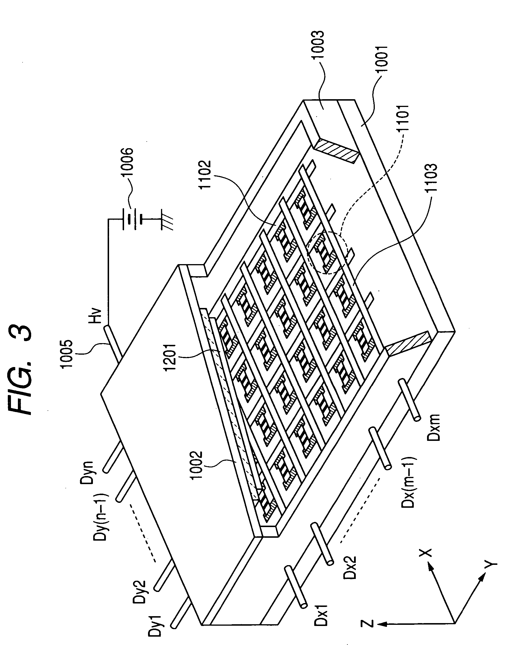
[0181]FIG. 3 is a perspective view of a display panel employed in the example, partially cut off in order to show an internal structure.

[0182] In FIG. 3, there are shown a bottom 1001 of a external envelope (also represented as a rear plate), a lateral wall 1003 and a face plate 1002, which constitute an air-tight container for maintaining the interior of the display panel in a vacuum state.

[0183] The rear plate 1001 and the face plate 1002 was maintained at a gap of 2 mm.

[0184] On the rear plate 1001, surface conduction electron emitting devices 1101 are formed by a number of M×N (M and N each being an integer of 2 or larger and suitably selected according to a desired number of pixels; N=240 and M=80 in the present example).

[0185] The N×M surface conduction electron emitting devices 1101 are wired in a simple matrix by M row wirings 1103 and N column wirings 110...

example 2

[0217] In the following, an example 2 of the present invention will be explained with reference to FIGS. 2, 3 and 4.

[0218] However, the image display apparatus employed in the second and subsequent examples is generally same as that in example 1, so that only characteristic portions of the present example will be explained in the following.

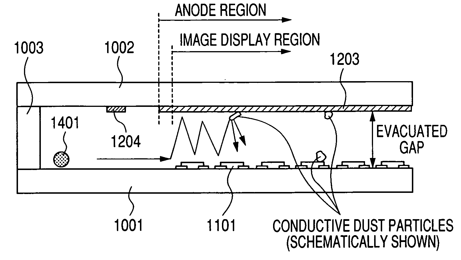
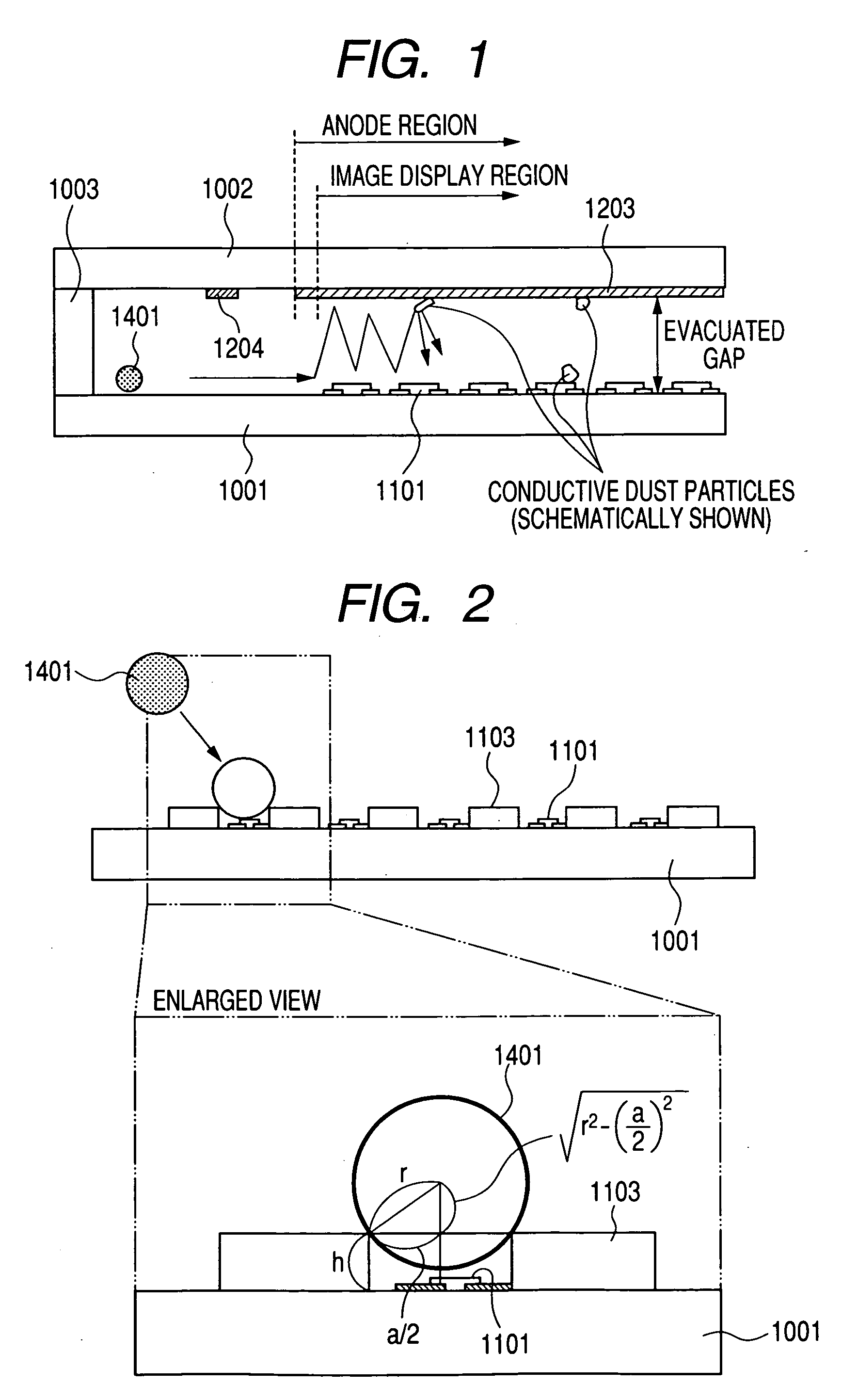
[0219] In a display panel maintained in vacuum by a rear plate 1001, a lateral wall 1003 and a face plate 1002 as in the example 1, controllable particles 1401 featuring the present invention are present in the vacuum container.

[0220] A magnetic force was employed for maintaining and displacing the controllable particles 1401 to the anode region, and magnetic conductive particles were employed as the controllable particles for causing a reciprocating motion by an electric field in the anode region.

[0221] The present example employed magnetic conductive-spherical nickel particles as the controllable particles, but this example is not restrictiv...

example 3

[0240] In the following, an example 2 of the present invention will be explained with reference to FIG. 5.

[0241] However, the image display apparatus employed in the present example is generally same as that in example 1, so that only characteristic parts of the present example will be explained in the following.

[0242] As in the example 1, in a display panel maintained in vacuum by a rear plate 1001, a lateral wall 1003 and a face plate 1002 as in the example 1, controllable particles 1401 featuring the present invention are present in the vacuum container.

[0243] As in the example 2, a magnetic force was employed for maintaining and displacing the controllable particles 1401 to the anode region, and magnetic conductive particles were employed as the controllable particles for causing a reciprocating motion by an electric field in the anode region.

[0244] The present example employed magnetic conductive spherical nickel particles as the controllable particles, but this example is ...


PUM


Abstract

The invention is to provide a flat panel display of excellent characteristics, not easily causing a discharge. For this purpose, the invention provides a producing method for an image display apparatus including a first substrate with an conductive surface, and a second substrate with an conductive surface opposed to the first substrate, the method including: a step of applying a voltage between the first substrate and the second substrate; and a step of introducing conductive particles into a space between the first substrate and the second substrate under the voltage application; wherein the voltage applied between the first substrate and the second substrate causes the introduced conductive particles to reciprocate between the first substrate and the second substrate and to collide with dust attached to the first or second substrate, thereby removing the dust from the first or second substrate.

Description

BACKGROUND OF THE INVENTION [0001] 1. Field of the Invention [0002] The present invention relates to a producing method for a substrate for an electronic device having a conductive member on a surface, and a cleaning apparatus. In particular, it relates to a producing method for an image display apparatus having a conductor on a surface and such an image display apparatus, and more particularly to a producing method for an image display apparatus utilizing an electron beam such as a field emission display (FED) and such an image display apparatus. [0003] 2. Related Background Art [0004] Non-patent Literature 1 describes a technology in which conductive particles execute a reciprocating motion between electrodes and go out of the electrodes. [0005] Also a method of moving dusts is described in Patent Literatures 1 and 2, utilizing the technology disclosed in Non-patent Literature 1. [0006] Also in image display apparatuses including cathode ray tube (CRT), developments are being made...

Claims


Application Information

Patent Timeline
Patent Type & Authority Applications(United States)
IPC IPC(8): H01J1/62H01J9/00H01J9/38
CPCH01J9/38H01J61/305H01J31/127
Inventor ONISHI, TOMOYA
Owner CANON KK
Why Eureka
Try Eureka