Impingement cooling system for a turbine blade
- Summary
- Abstract
- Description
- Claims
- Application Information
AI Technical Summary
Benefits of technology
Problems solved by technology
Method used
Image
Examples
Embodiment Construction
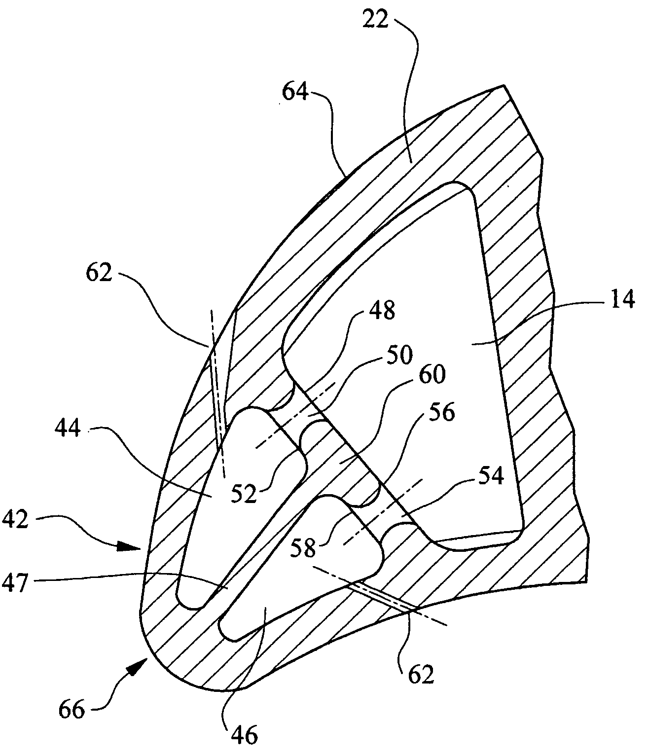
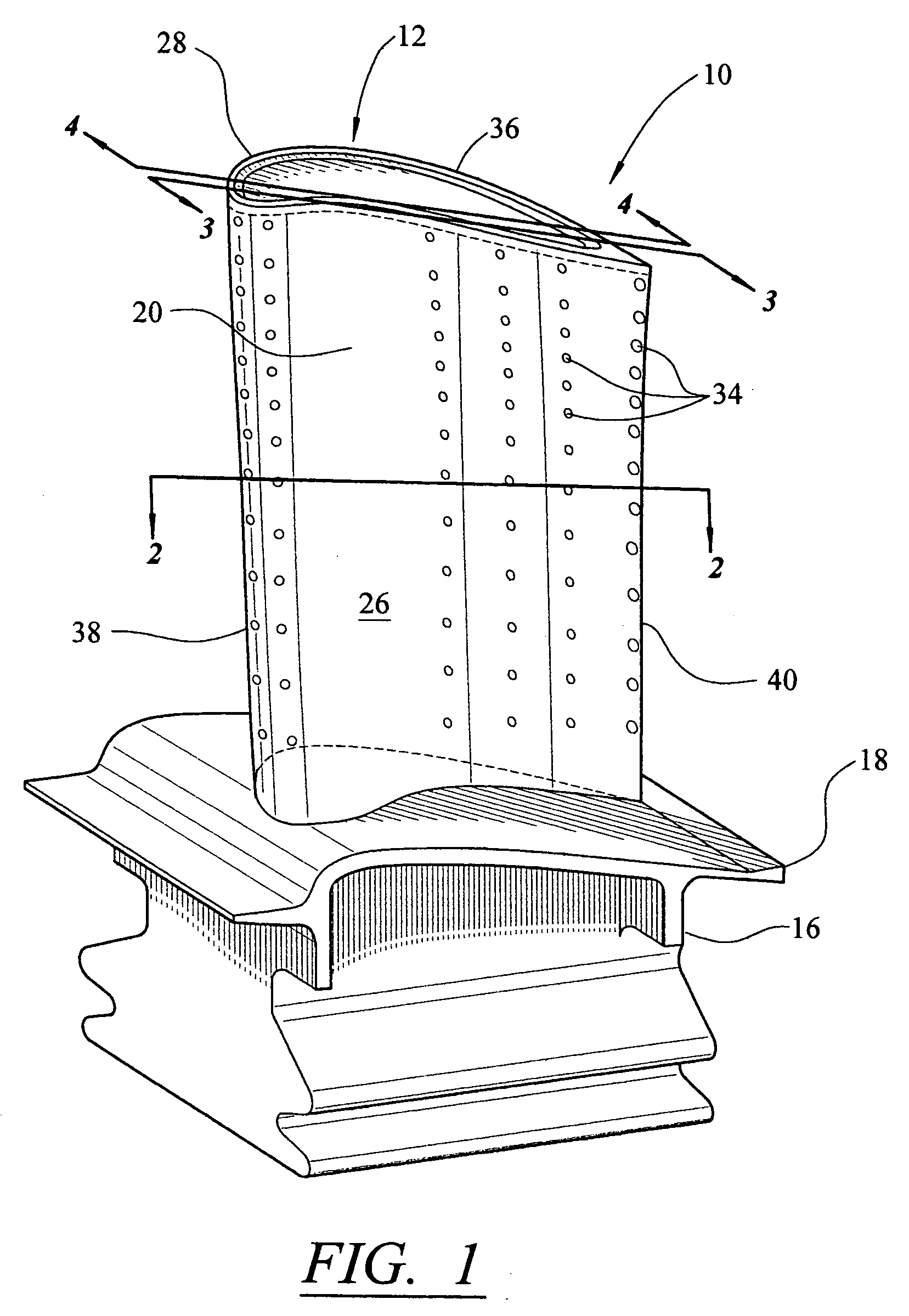
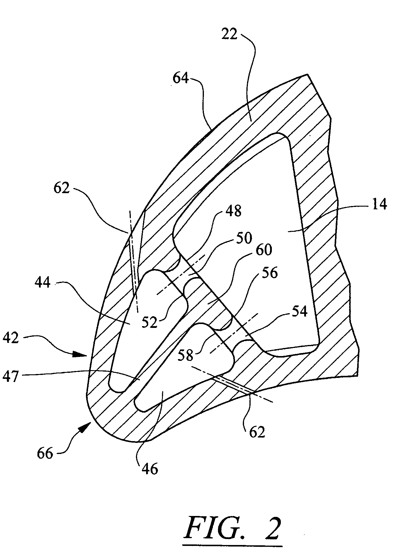
[0021] As shown in FIGS. 1-5, this invention is directed to a turbine blade cooling system 10 for turbine blades 12 used in turbine engines. In particular, turbine blade cooling system 10 is directed to a cooling system 10 located in a cavity 14, as shown in FIGS. 3 and 4, positioned between outer walls 22. Outer walls 22 form a housing 24 of the turbine blade 12. As shown in FIG. 1, the turbine blade 12 may be formed from a root 16 having a platform 18 and a generally elongated blade 20 coupled to the root 16 at the platform 18. The turbine blade may also include a tip 36 generally opposite the root 16 and the platform 18. Blade 20 may have an outer wall 22 adapted for use, for example, in a first stage of an axial flow turbine engine. Outer wall 22 may have a generally concave shaped portion forming pressure side 26 and may have a generally convex shaped portion forming suction side 28.
[0022] The cavity 14, as shown in FIGS. 3 and 4, may be positioned in inner aspects of the blad...
PUM
 Abstract
Description
Claims
Application Information
 - R&D
- Intellectual Property
- Life Sciences
- Materials
- Tech Scout
- Unparalleled Data Quality
- Higher Quality Content
- 60% Fewer Hallucinations
Browse by: Latest US Patents, China's latest patents, Technical Efficacy Thesaurus, Application Domain, Technology Topic, Popular Technical Reports.
© 2025 PatSnap. All rights reserved.Legal|Privacy policy|Modern Slavery Act Transparency Statement|Sitemap|About US| Contact US: help@patsnap.com


