
Intrabody introduced device and medical device

a technology of introduced devices and medical devices, which is applied in the field of introduced devices, can solve the problems of reducing the threshold, the difficulty of the receiver in binarizing synchronizing signals, etc., and achieves the effect of favorable image signals and stable binarizing synchronizing signals

Inactive Publication Date: 2006-01-05
OLYMPUS CORP
View PDF13 Cites 14 Cited by
  • Summary
  • Abstract
  • Description
  • Claims
  • Application Information

AI Technical Summary

Benefits of technology

[0012] For example, in the same high-frequency band as the image signals, signals having signal levels not used for image signals are assumed synchronizing signals. Thereby, the fluctuation in the DC levels of the synchronizing signals can be reduced to stabilize binarization of the synchronizing signals. Furthermore, the image signals can be favorably separated from the synchronizing signals.
[0014] In this condition, a receiver can distinguish the image signals clipped by the clipping section from the synchronizing signals set by the setting section by means of the signal levels. The clipping section clips the signal levels of the image signals so as to prevent the signal levels of the image signals from being mixed with the signal levels allocated to the synchronizing signals.
[0019] The intrabody introduced device or the medical device according to the present invention is capable of setting synchronizing signals in the same high-frequency band as image signals and in signal patterns not used for image signals. This enables the receiver to stably binarize the synchronizing signals and thus acquire favorable image signals.

Problems solved by technology

The capsule type endoscopes of the prior art can incorrectly recognize synchronizing signals as image information, and in such case, may use the synchronizing signals having signal patterns included in the image information.
Therefore, when the synchronizing signals are binarized at a predetermined level (a threshold value), a margin of the threshold is decreased due to the fluctuation of the DC level, so the receiver has a difficulty to binarize the synchronizing signals.

Method used


Image

  • Intrabody introduced device and medical device
  • Intrabody introduced device and medical device
  • Intrabody introduced device and medical device

Examples


first embodiment

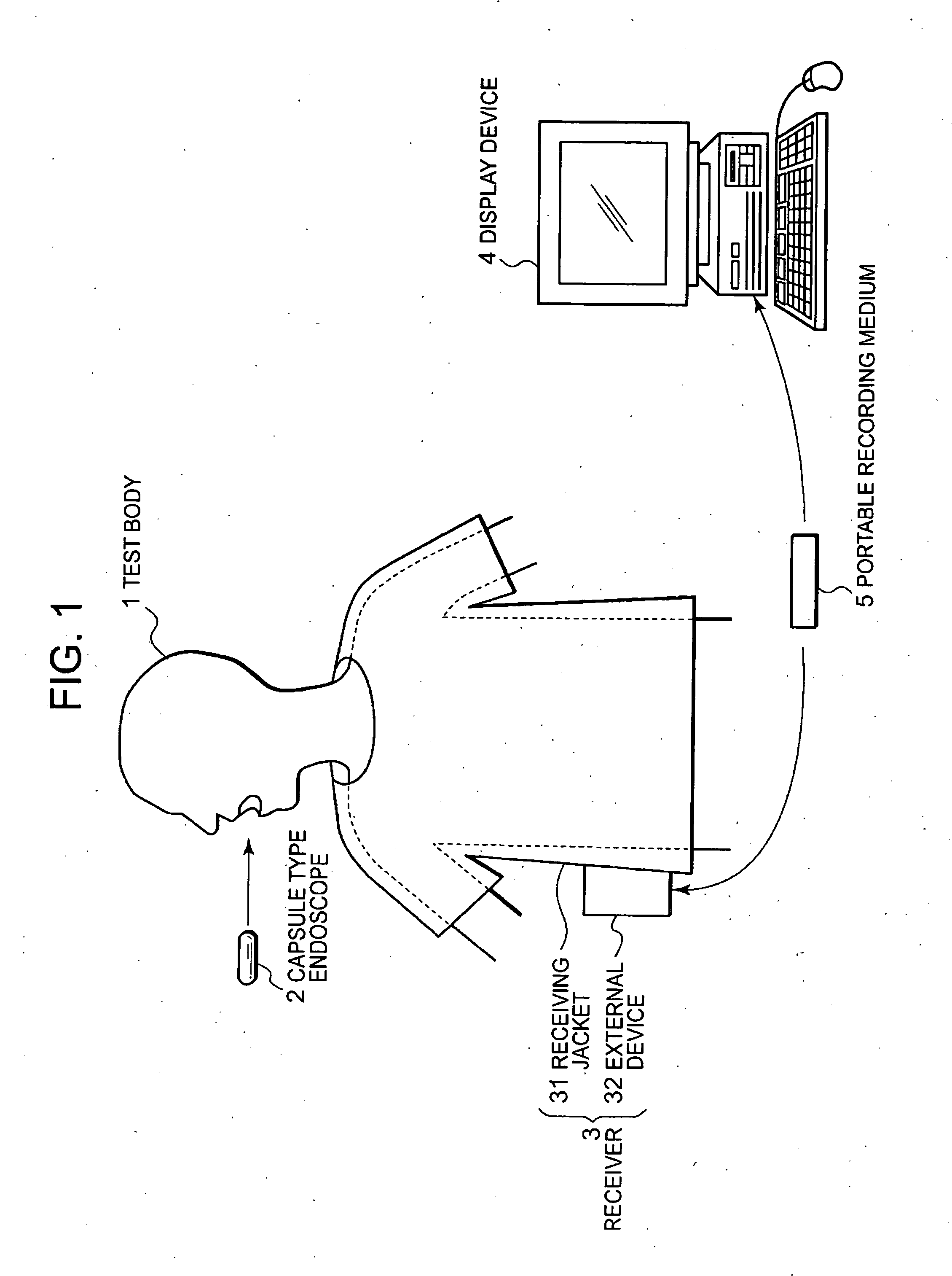
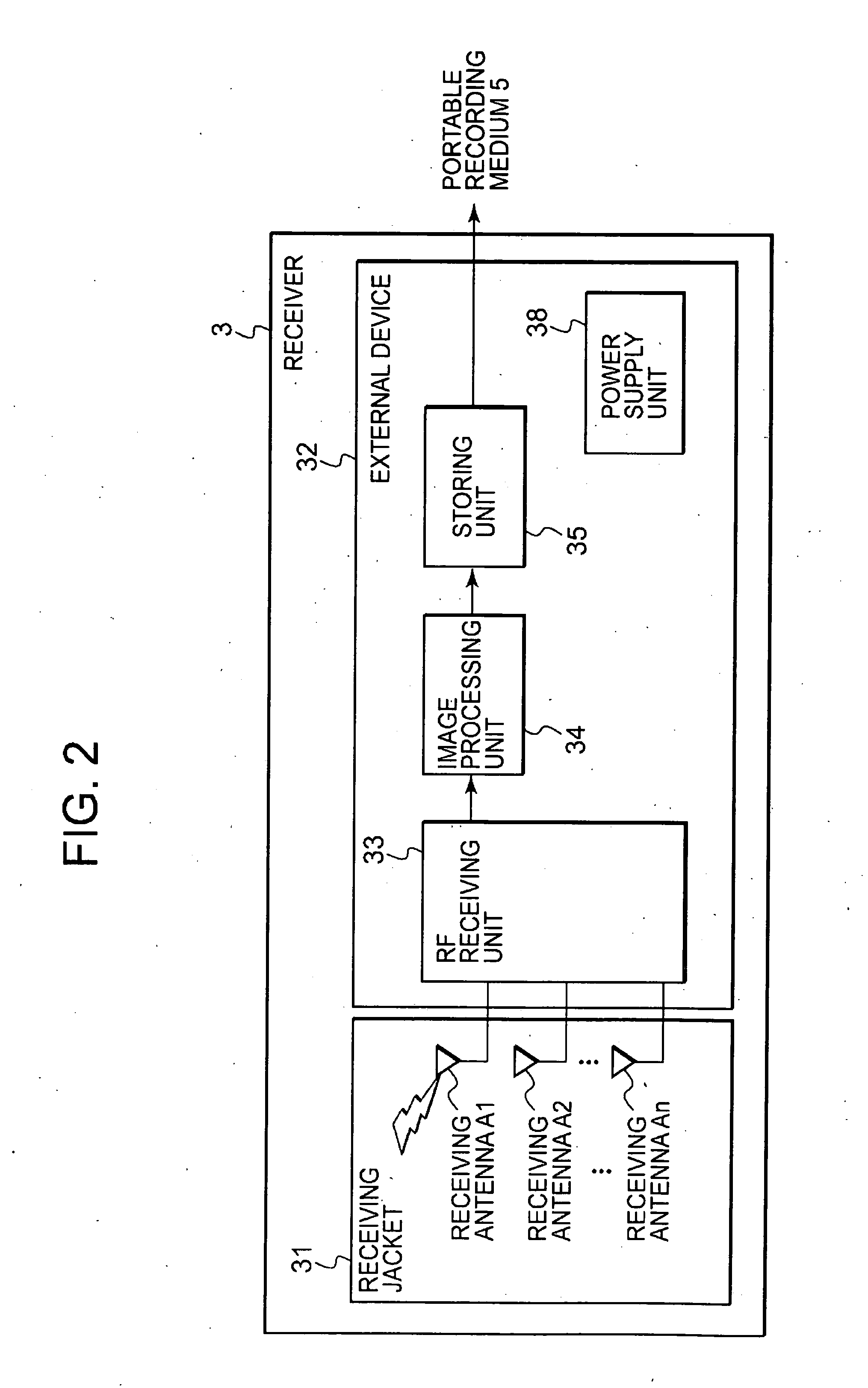
[0033] Referring to FIG. 1, there is shown a schematic diagram of a general configuration of a wireless intrabody information acquisition system including an intrabody introduced device according to a This wireless intrabody information acquisition system will now be described below by giving an example of a capsule type endoscope as the intrabody introduced device. Those skilled in the art will appreciate that the capsule type endoscope is used by way of example only and that other intrabody introduced devices can also be used without departing from the spirit and scope of the claimed invention. In FIG. 1, the wireless intrabody information acquisition system comprises a receiver 3 having a wireless receiving function and a capsule type endoscope (intrabody introduced device) 2, which is introduced into a test body 1 to capture images of the inside of the body cavity and transmit data such as image signals to the receiver 3. The wireless intrabody information acquisition system fu...

second embodiment

[0050] Referring to FIG. 9, there is shown a block diagram of the image pickup timing system shown in FIG. 3 in a Referring to FIG. 10, there is shown a block diagram of a detailed configuration of the image processing unit in the external device shown in FIG. 2.

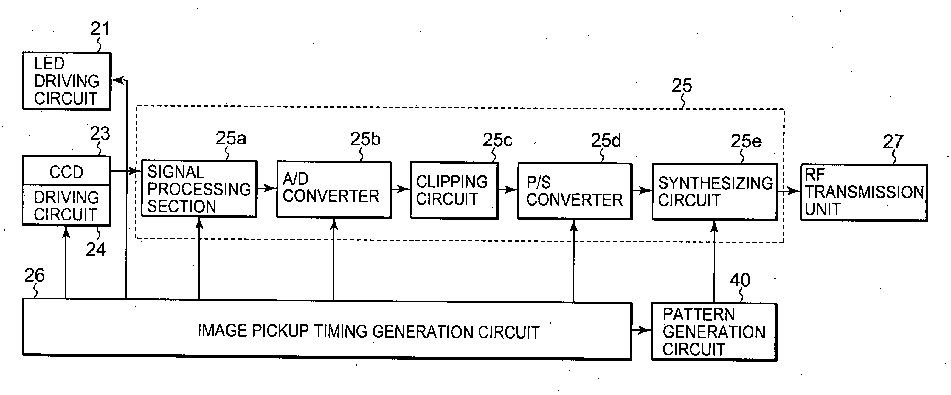
[0051] In the second embodiment, the image pickup timing system and the image processing unit differ from those shown in FIG. 4 and FIG. 6 as described below. The image pickup timing system differs from one shown in FIG. 4 in that it is provided with a signal selection inverter 25f in the subsequent stage of a clipping circuit 25c of a signal processing circuit 25. The signal selection inverter 25f selects image information on signal patterns of relatively high frequencies out of the acquired image information and converts the specific signal patterns to signal patterns of a high-intensity portion clipped by the clipping circuit 25c. The signal selection inverter 25f selects the image information on the specific signal patt...


PUM


Abstract

In transmitting images picked up by an intrabody introduced device to outside a test body, synchronizing signals of the image signal are set to signal patterns in the same high-frequency band as for the image signal and not used for the image signal. This enables a receiver to stably binarize the synchronizing signal and thus to acquire favorable image signal. For example, in a clipping circuit provided in a signal processing circuit in a capsule type endoscope (an example of an intrabody introduced device), image information of a high-intensity portion is clipped out of image information acquired by an imaging section and a pattern generation circuit allocates signal patterns within the clipped intensity range as horizontal and vertical synchronizing signals.

Description

CROSS-REFERENCE TO RELATED APPLICATION [0001] This application is based upon and claims the benefit of priority from prior Japanese Patent Application No. 2004-153894, filed May 24, 2004, the entire contents of which is incorporated herein by reference. BACKGROUND OF THE INVENTION [0002] 1. Field of the Invention [0003] The present invention relates to an intrabody introduced device, which is introduced into a test body, or a medical device including the intrabody introduced device. This type of intrabody introduced device includes, for example, a swallowable capsule type endoscope. [0004] 2. Description of the Related Art [0005] In recent years, a capsule type endoscope having an imaging function and a wireless function has emerged as one of the intrabody introduced devices in the endoscope area. The capsule type endoscope is swallowed by a test subject as a test body for observation (examination) and then moves inside the stomach, the small intestine, or other organs (in the body ...

Claims


Application Information

Patent Timeline
Patent Type & Authority Applications(United States)
IPC IPC(8): A61B1/04A61B5/07A61B1/00A61B1/05G06T1/00G06T5/00
CPCA61B1/041A61B1/0684A61B1/0676
Inventor SHIGEMORI, TOSHIAKIMORI, TAKESHI
Owner OLYMPUS CORP
Learn More