Error detecting circuit

a technology of error detection and circuit, applied in the field of electronic devices, can solve the problems of soft errors mainly caused, soft errors are gaining in importance even for terrestrial applications, and individual soft error rates of circuit blocks

Inactive Publication Date: 2006-01-05
INTEL CORP
View PDF8 Cites 23 Cited by
  • Summary
  • Abstract
  • Description
  • Claims
  • Application Information

AI Technical Summary

Problems solved by technology

Soft errors are mainly caused by radiation due to neutrons generated by cosmic rays from deep space and alpha particles from packaging material.
Traditionally, soft errors are a major cause of concern mainly for space applications.
However, for designs manufactured at technology nodes 130 nm and below, soft errors are gaining in importance even for terrestrial applications.
Soft error rates of individual circuit blocks (e.g., memory cells) have not significantly increased over technology generations; however, an increased number of transistors inside a single chip results in increased chip level error rate.
In addition to these soft errors, errors are generated in latches due to general noise and amplifier errors.
Corrupted latches and flip-flops may lead to incorrect machine states resulting in silent data corruption or system crash depending on where and when the error occurred.
For example, errors in datapath latches or flip-flops may lead to silent data corruption if the errors are left undetected.
While scan and other Design-For-Testability (DFT) mechanisms address manufacturing tests, they are not used in normal operation in the field.

Method used


Image

  • Error detecting circuit
  • Error detecting circuit
  • Error detecting circuit

Examples


Embodiment Construction

[0017] In the following description, for purposes of explanation, numerous details are set forth in order to provide a thorough understanding of the disclosed embodiments of the present invention. However, it will be apparent to one skilled in the art that these specific details are not required in order to practice the disclosed embodiments of the present invention. In other instances, well-known electrical structures and circuits are shown in block diagram form in order not to obscure the disclosed embodiments of the present invention.

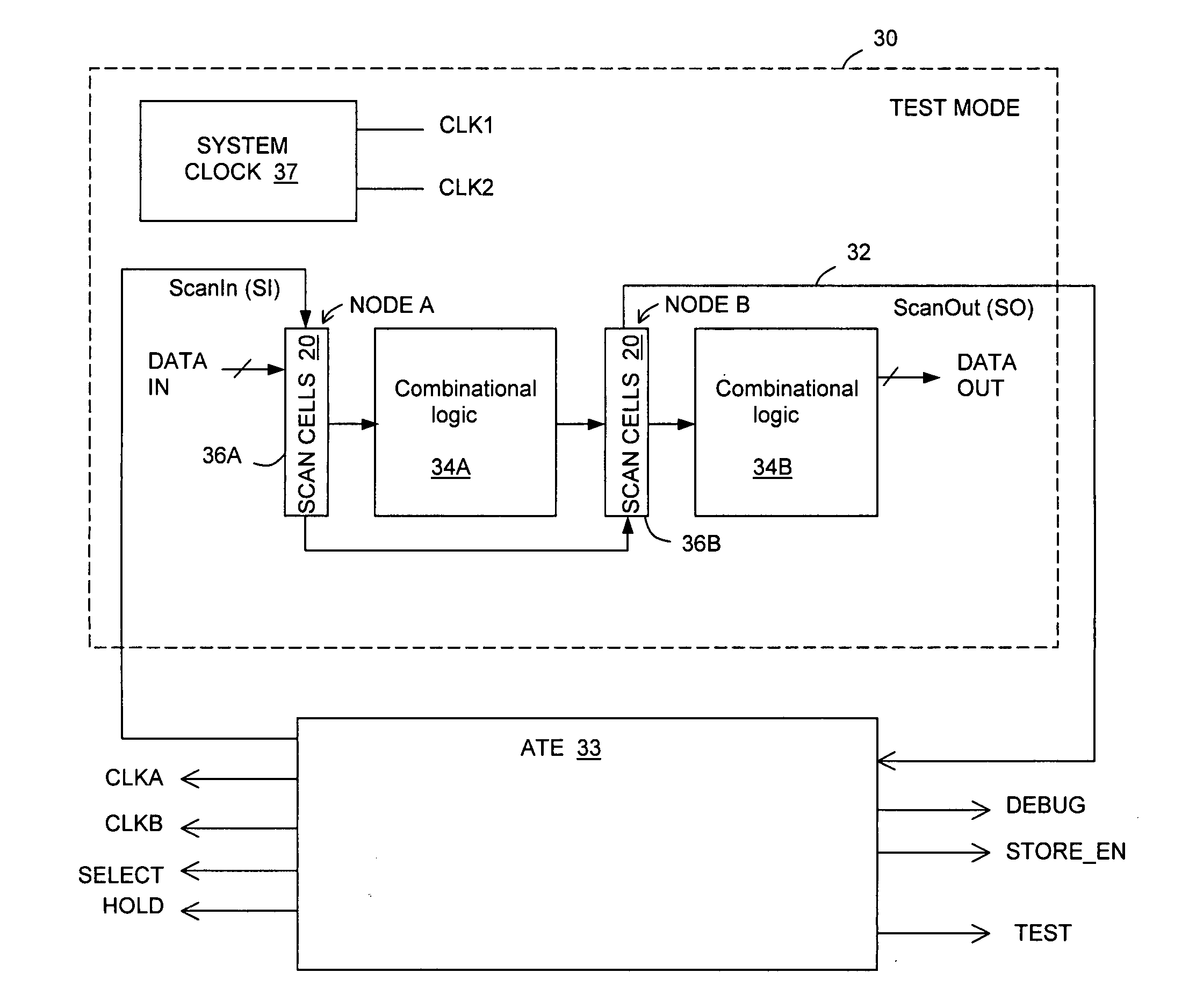
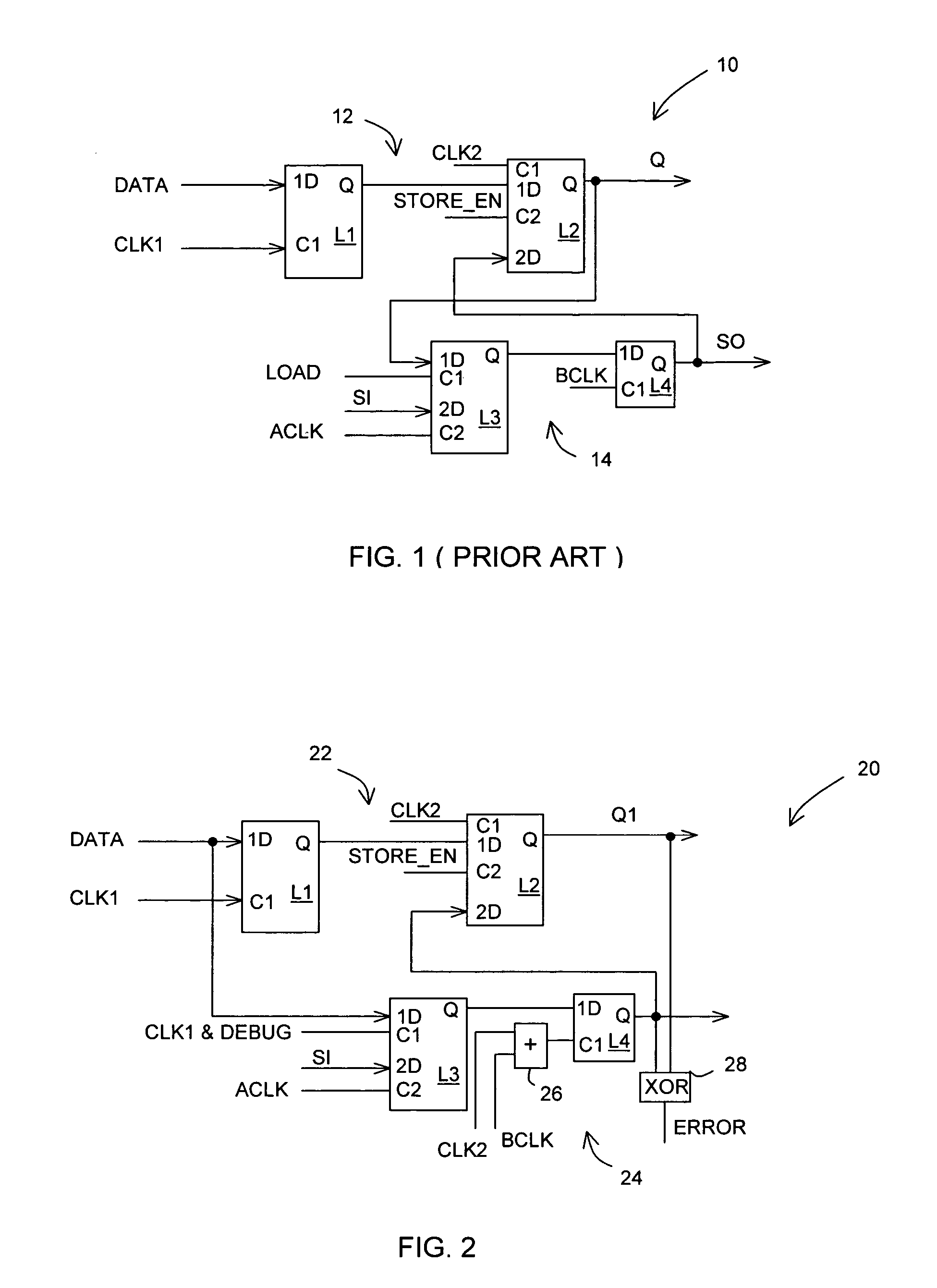
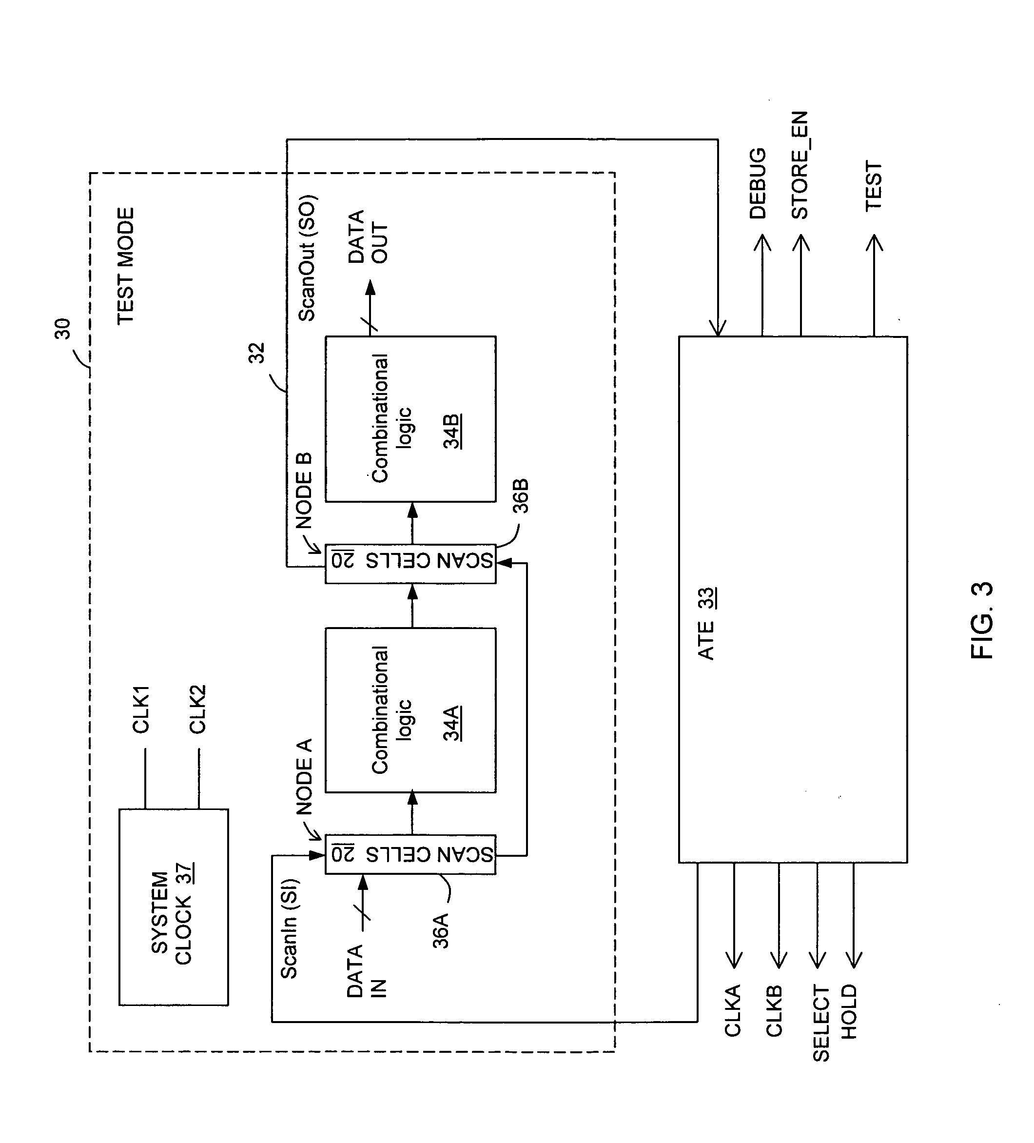
[0018] Referring to FIG. 2, there is illustrated a self-checking, full-hold scan cell 20, in accordance with one embodiment of the invention, for an integrated circuit (IC) chip (not shown). The scan cell 20 has DFT resources available on-chip for scan-based structural testing purposes, as described with respect to FIG. 1. In the prior art approach, these DFT resources are not used after manufacturing testing when the IC chip is distributed into the...


PUM


Abstract

In one embodiment, an apparatus includes a datapath circuit to generate a data output signal in response to a data input signal and at least a first data clock signal; a shadow circuit, coupled to the datapath circuit, to generate a shadow output signal in response the data input signal and at least a second data clock signal during a functional mode of operation and to generate a scan-out signal in response to a scan-in signal and at least a first test clock signal during a test mode of operation; and an error detect circuit, coupled to the datapath and the shadow circuits, to generate an error signal in response to a mismatch between the data output signal and the shadow output signal.

Description

BACKGROUND OF THE INVENTION [0001] 1. Field of the Invention [0002] The present invention relates to electronic devices, and in particular, to errors in electronic devices. [0003] 2. Description of Related Art [0004] Radiation-induced transient errors in digital systems are often referred to as single event upsets (SEUs) or soft errors. Soft errors are mainly caused by radiation due to neutrons generated by cosmic rays from deep space and alpha particles from packaging material. Traditionally, soft errors are a major cause of concern mainly for space applications. However, for designs manufactured at technology nodes 130 nm and below, soft errors are gaining in importance even for terrestrial applications. Examples include processors and networking equipments targeted for high RAS (Reliability, Availability and Serviceability) applications. A major reason for increased significance of soft errors is the increased number of transistors inside an integrated circuit chip. Soft error ra...

Claims


Application Information

Patent Timeline
Patent Type & Authority Applications(United States)
IPC IPC(8): G01R31/28
CPCG01R31/31816G11C2029/3202G01R31/318566G01R31/318541
Inventor MITRA, SUBHASISHKIM, KEE S.MAK, TAK M.GOTETI, PRASHANT M.
Owner INTEL CORP
Why Eureka
Try Eureka