High intensity refiner plate with inner fiberizing zone

a technology of fiberizing zone and refiner plate, which is applied in the direction of pretreatment with water/steam, manufacturing tools, grain treatment, etc., to achieve the effect of minimizing equipment components, space, and energy efficiency

Inactive Publication Date: 2006-01-12
ANDRITZ INC
View PDF5 Cites 18 Cited by
  • Summary
  • Abstract
  • Description
  • Claims
  • Application Information

AI Technical Summary

Benefits of technology

[0005] The object of the invention is to provide a refiner plate configuration that promotes the production of high quality thermomechanical pulps at lower energy consumption.
[0006] In essence, the invention achieves significant energy efficiency, even in systems that do not employ a high speed refiner, while reducing the scope and complexity of the equipment needed upstream of the refiner.

Problems solved by technology

However, especially for systems that did not employ high-speed refiners, the long-term energy efficiency was offset to some extent in the short term by the need for more costly or more space-occupying equipment upstream of the primary refiner.

Method used


Image

  • High intensity refiner plate with inner fiberizing zone
  • High intensity refiner plate with inner fiberizing zone
  • High intensity refiner plate with inner fiberizing zone

Examples


Embodiment Construction

1. Overview

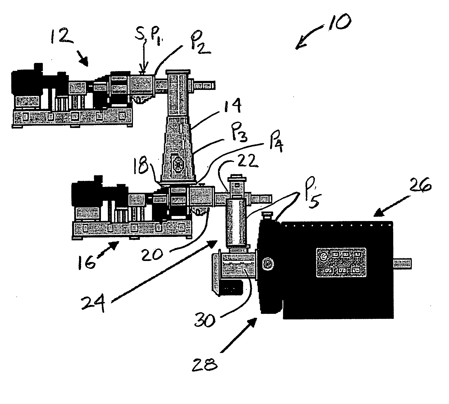
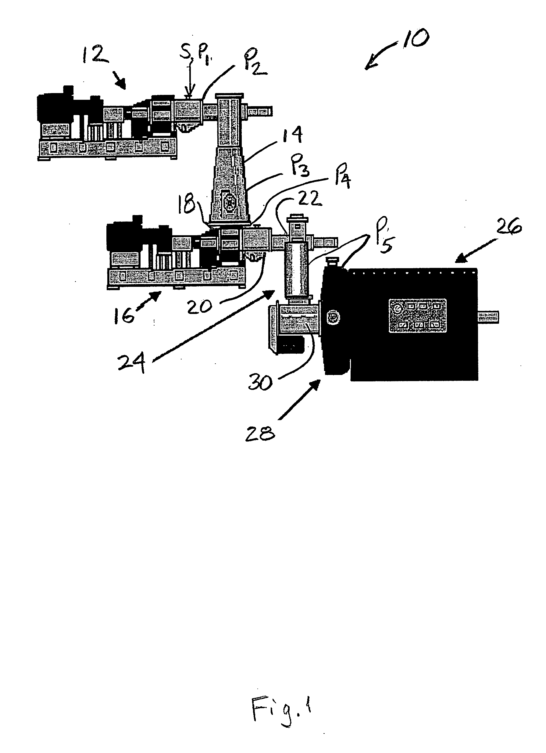
[0039]FIG. 1 shows a TMP refiner system 10 according to the preferred embodiment of the invention. A standard atmospheric inlet plug screw feeder 12 receives presteamed (softened) chips from source S at atmospheric pressure P1=0 psig and delivers pre-steamed wood chips at pressure P2=0 psig to a steam tube 14 where the chips are exposed to an environment of saturated steam at a pressure P3. Depending on the system configuration, the pressure P3 can range from atmospheric to about 15 psig or from 15 to up to about 25 psig with holding times in the range of a few seconds to many minutes. The chips are delivered to a macerating pressurized plug screw discharger 16.

[0040] The macerating pressurized plug screw discharger 16 has an inlet end 18 at a pressure P4 in the range of about 5 to 25 psig, for receiving the steamed chips. Preferably, the macerating pressurized screw discharger has an inlet pressure P4 that is the same as the pressure P3 in the steam tube 14. The macer...


PUM

PropertyMeasurementUnit
diameteraaaaaaaaaa
pressureaaaaaaaaaa
pressureaaaaaaaaaa

Abstract

Plate elements, a plate configuration, and associated system for thermomechanical refining of wood chips wherein destructured and partially defibrated chips are fed to a rotating disc primary refiner, where opposed discs each have an inner band pattern of bars and grooves and outer band pattern of bars and grooves, such that substantially complete fiberization (defibration) of the chips is achieved in the inner band and the resulting fibers are fibrillated in the outer band. One embodiment is directed to a pair of opposed co-operating refining plate elements for a flat disc refiner wherein the bars and grooves on each of the inner bands form an inner feed region followed by an outer working region, the bars and groove on each of the outer bands form an inner feed region followed by an outer working region, and the gap and / or material flow area formed when the plates are placed in front of each other increases between the inner working region and the outer feed region.

Description

RELATED APPLICATION [0001] This application is a continuation-in-part of pending U.S. application Ser. No. 10 / 888,135 filed Jul. 8, 2004, entitled, “Energy Efficient TMP Refining of Destructured Chips”, the benefit of which is claimed under 35 U.S.C. 120 and 121, and the disclosure of which is incorporated by reference.BACKGROUND OF THE INVENTION [0002] The present invention relates to apparatus and method for thermomechanical pulping of lignocellulosic material, particularly wood chips. [0003] In recent decades, the quality of mechanical pulp produced by thermomechanical pulping (TMP) techniques has been improving, but the rising cost of energy for these energy-intensive techniques imposes even greater incentives for energy efficiency while maintaining quality. The underlying principle in the progression of recent developments toward energy efficiency while maintaining quality, has been to distinguish and handle in distinct equipment, the axial fiber separation and fiberization of ...

Claims


Application Information

Patent Timeline
Patent Type & Authority Applications(United States)
IPC IPC(8): B02C7/06B02C7/12D21BD21D1/30
CPCB02C7/12D21B1/02D21D1/306D21D1/30D21B1/12
Inventor SABOURIN, MARC J.GINGRAS, LUC
Owner ANDRITZ INC
Why Eureka
Try Eureka