
Reformer, fuel cell system having the same, and method of manufacturing the same

a fuel cell system and reformer technology, applied in the field of fuel cell systems, can solve the problems of deteriorating reaction efficiency and thermal efficiency of the entire fuel cell system, and achieve the effects of simple structure, reduced size and improved performan

Inactive Publication Date: 2006-01-12
SAMSUNG SDI CO LTD
View PDF3 Cites 7 Cited by
  • Summary
  • Abstract
  • Description
  • Claims
  • Application Information

AI Technical Summary

Benefits of technology

[0008] An embodiment of the present invention provides a reformer which can be decreased in size and improve performance with a simple structure. According to another embodiment, a fuel cell system is provided having the reformer.
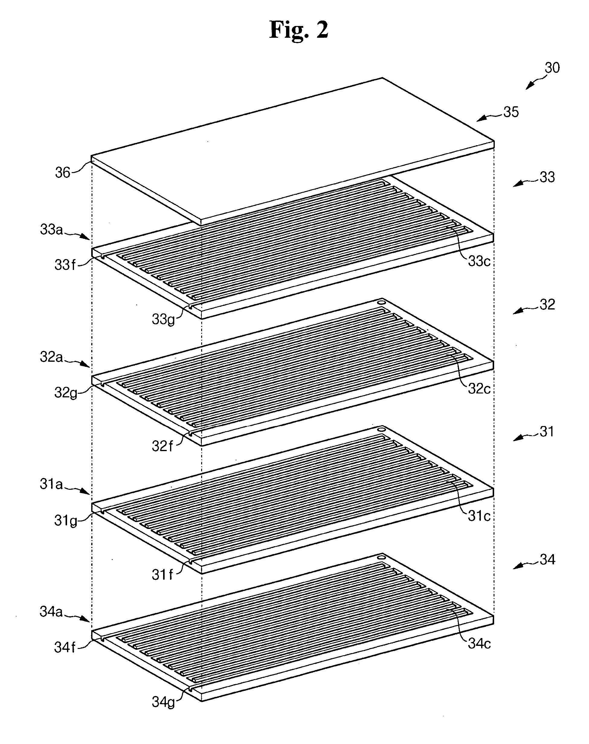
[0012] The plurality of plates and at least one catalyst layer constitute a plurality of reaction sections, and each of the plurality of reaction sections includes a plate of the plurality of plates having a channel, a cover plate of the plurality of plates contacting the plate having the channel to form a passage and a catalyst layer formed on inner surfaces of the passage, respectively. Here, the plurality of reaction sections may include a heat source adapted to generate thermal energy, a reforming reactor adapted to generate hydrogen gas from the fuel, and a carbon-monoxide reducer adapted to reduce a concentration of carbon monoxide contained in the hydrogen gas.

Problems solved by technology

Accordingly, it is difficult to compactly embody the fuel cell system and to rapidly deliver the thermal energy generated from the heat source to the reforming reactor, thereby deteriorating reaction efficiency and thermal efficiency of the entire fuel cell system.

Method used


Image

  • Reformer, fuel cell system having the same, and method of manufacturing the same
  • Reformer, fuel cell system having the same, and method of manufacturing the same
  • Reformer, fuel cell system having the same, and method of manufacturing the same

Examples


Embodiment Construction

[0033] Hereinafter, exemplary embodiments of the present invention will be described in detail with reference to the attached drawings such that the present invention can be easily put into practice by those skilled in the art. However, the present invention is not limited to the exemplary embodiments, and may be embodied in various forms.

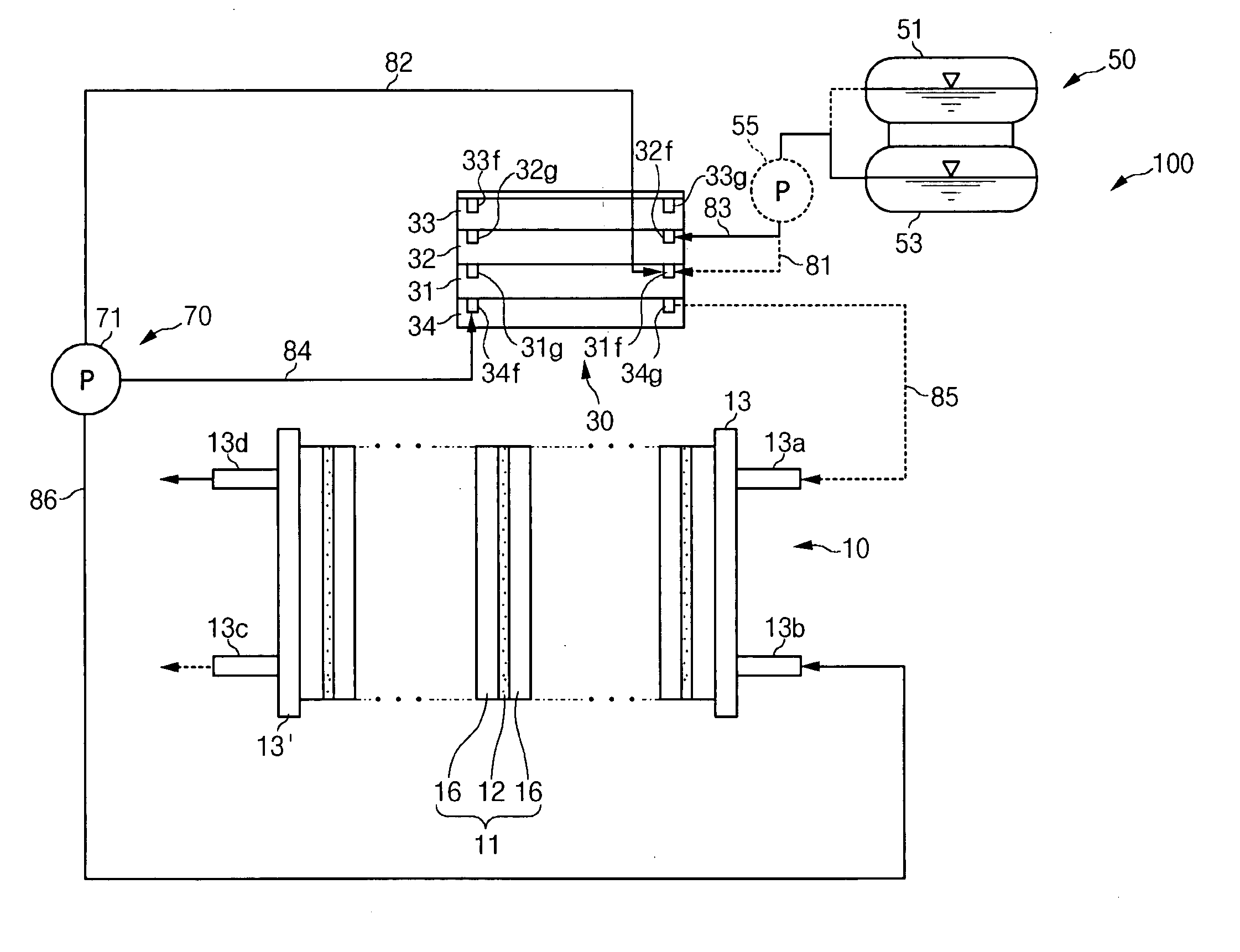
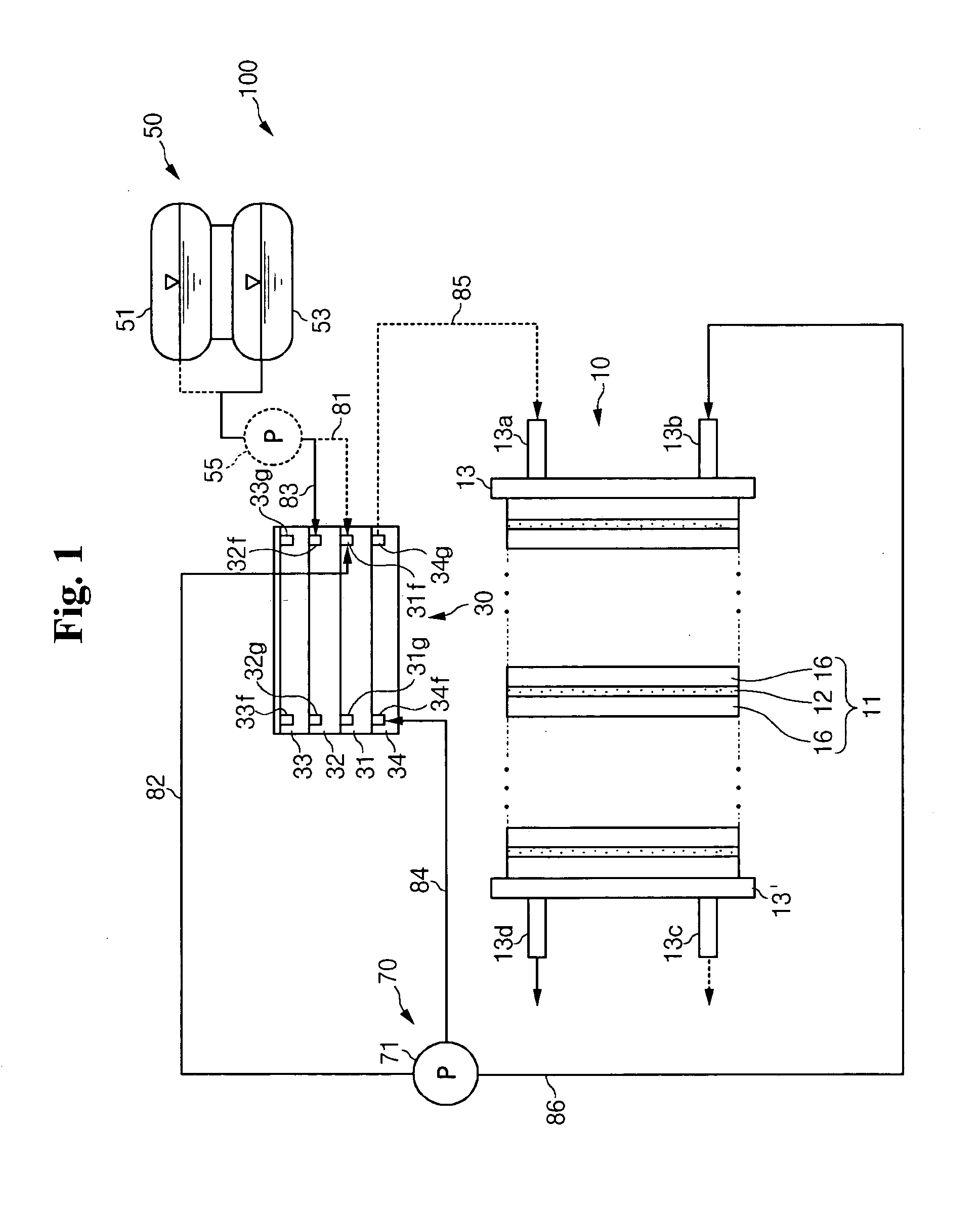
[0034]FIG. 1 is a schematic diagram illustrating an entire construction of a fuel cell system according to an embodiment of the present invention.

[0035] The fuel used to generate electricity in the fuel cell system 100 according to the present invention can include a liquid or gas hydrogen-containing fuel such as methanol, ethanol, or natural gas. However, liquid fuel is exemplified as the fuel in the following description.

[0036] The fuel cell system 100 may utilize pure oxygen stored in an additional storage device for reacting with hydrogen contained in the fuel or may utilize oxygen-containing air as the necessary oxygen source. However, the ...


PUM

PropertyMeasurementUnit
Electric energyaaaaaaaaaa
Pressureaaaaaaaaaa
Concentrationaaaaaaaaaa

Abstract

A fuel cell system includes: a reformer adapted to generate hydrogen from a fuel containing hydrogen through a chemical catalytic reaction using thermal energy; at least one electricity generator adapted to generate electric energy through an electrochemical reaction of hydrogen and oxygen; a fuel supply unit adapted to supply the fuel to the reformer; and an air supply unit adapted to supply oxygen to the reformer and the at least one electricity generator. The reformer includes a plurality of plates stacked with each other and forming at least one passage adapted to allow a fuel or a gas to flow therethrough and at least one catalyst layer coated on inner surfaces of the at least one passage. In the reformer, the at least one catalyst layer is formed to have a plurality of grooves extending substantially in a same direction as of the at least one passage.

Description

CROSS-REFERENCE TO RELATED APPLICATION [0001] This application claims priority to and the benefit of Korean Patent Application 10-2004-0049294 filed in the Korean Intellectual Property Office on Jun. 29, 2004, the entire content of which is incorporated herein by reference. FIELD OF THE INVENTION [0002] The present invention relates to a fuel cell system and more particularly to a plate type reformer for a fuel cell system. BACKGROUND OF THE INVENTION [0003] A fuel cell is an electricity generating system that directly converts chemical reaction energy of oxygen and hydrogen contained in hydrocarbon materials such as methanol, ethanol, or natural gas into electric energy. [0004] A polymer electrolyte membrane fuel cell (hereinafter, referred to as PEMFC) has been developed recently which has excellent output characteristics, low operating temperatures, and fast starting and response characteristics. PEMFCs have a wide range of application, including mobile power sources for vehicles...

Claims


Application Information

Patent Timeline
IPC IPC(8): H01M8/00
CPCH01M8/04007Y02E60/50H01M8/0631Y02P70/50H01M8/04H01M8/06
Inventor PARK, ZINKIM, JU-YONGLIM, HYUN-JEONGHAN, JI-SEONGKWEON, HO-JIN
Owner SAMSUNG SDI CO LTD
Learn More