Method and device for kinematic retaining cervical plating

Inactive Publication Date: 2006-01-12
SPINEFRONTIER LLS
View PDF8 Cites 50 Cited by
  • Summary
  • Abstract
  • Description
  • Claims
  • Application Information

AI Technical Summary

Benefits of technology

[0015] Among the advantages of this invention may be one or more of the following. The implantable graft and kinematic retaining plates stabilize the spine, while allowing the patient to retain spinal flexibility by preserving motion between adjacent vertebras. The design of the plates allows for easy placement of the plates and screws because the plates are attached to only one vertebral body. The tongue and groove attachment configurati

Problems solved by technology

Although, current plating systems offer these advantages, there is a growing body of data that document significant failure rates for reconstruction with plates after multilevel anterior corpectomy and fusion.
It is believed that the long lever arm of the plate especially across two or more vertebral corpectomies leads to pullout of the screws 25 and dislodgement of the plate 27 which can result in esophageal erosion and death.
It is also technically challenging to place a plate 27 across two or more disc spaces while maintaining the correct length and avoid

Method used


Image

  • Method and device for kinematic retaining cervical plating
  • Method and device for kinematic retaining cervical plating
  • Method and device for kinematic retaining cervical plating

Examples


Example

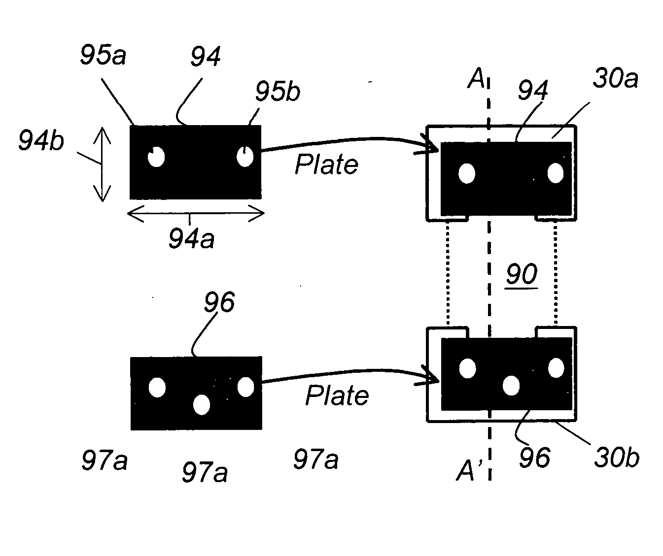
[0033] Referring to FIG. 2, a new grafting technique for replacing an intervertebral disc 40 includes first removing the intervertebral disc 40 form the space between two adjacent vertebras 30a, 30b, then forming grooves 32a, 32b in vertebras 30a, 30b, respectively, then preparing a graft 90 and inserting the graft in the space between the vertebras 30a, 30b. The graft 90 is either an autograft or an allograft and includes tongue extensions 92a, 92b extending from the top 91a and bottom 91b of the graft 90, respectively. The tongue extensions 92a, 92b are designed to fit closely in grooves 32a, 32b, respectively, in a tongue and groove or “dovetail” attachment configuration. The tongue and groove attachment configuration provides multidirectional stability and allows immediate range of motion of the spine without the need for external bracing. In one example, shown in FIG. 4, the groove 32a, has dimensions 33a, 33b, 33c of 3 mm, 10 mm, 5 mm, respectively. The dimension 33b is usuall...


PUM

PropertyMeasurementUnit
Structureaaaaaaaaaa
Elasticityaaaaaaaaaa
Biodegradabilityaaaaaaaaaa

Abstract

A spinal implant assembly for replacing intervertebral elements between a first spinal vertebra and an adjacent second spinal vertebra includes an intervertebral implant for inserting between the first and second spinal vertebrae and a first kinematic retaining plate. The intervertebral implant comprises a body having a top surface, a bottom surface, and a first appendage extending from the top surface of the intervertebral implant. The first appendage is adapted to fit within and form a tongue and groove attachment with a first opening formed in the first spinal vertebra. The first kinematic retaining plate is attached to the first spinal vertebra so that it secures the first appendage in the first opening. The intervertebral implant further comprises a second appendage extending from the bottom surface and the second appendage is adapted to fit within and form a tongue and groove attachment with a second opening formed in the second spinal vertebra. A second kinematic retaining plate is attached to the second spinal vertebra so that it secures the second appendage in the second opening.

Description

CROSS REFERENCE TO RELATED CO-PENDING APPLICATIONS [0001] This application claims the benefit of U.S. provisional application Ser. No. 60 / 586,761 filed on Jul. 8, 2004 and entitled METHODS AND DEVICES FOR KINEMATIC RETAINING CERVICAL (KRC) PLATING which is commonly assigned and the contents of which are expressly incorporated herein by reference.FIELD OF THE INVENTION [0002] The present invention relates to an apparatus and a method for connecting and stabilizing spinal vertebrae, and more particularly to an apparatus and a method that connects spinal vertebrae while preserving spinal stability and mobility. BACKGROUND OF THE INVENTION [0003] The human spine 29 comprises individual vertebras 30 (segments) that are connected to each other to form a spinal column, shown in FIG. 1A. The vertebras 30 are separated and cushioned by thin pads of tough, resilient fiber known as inter-vertebral discs 40, shown in FIG. 1B. Inter-vertebral discs 40 provide flexibility to the spine 29 and act ...

Claims


Application Information

Patent Timeline
IPC IPC(8): A61F2/44A61B17/70
CPCA61B17/7059A61F2310/00359A61F2/442A61F2/4425A61F2002/2835A61F2002/30062A61F2002/30383A61F2002/30649A61F2002/30795A61F2002/3082A61F2002/30841A61F2002/30883A61F2002/30904A61F2210/0004A61F2220/0025A61F2310/00017A61F2310/00023A61F2310/00293A61F2310/00401A61F2310/00407A61F2310/00413A61F2310/00568A61F2310/0058A61F2310/00592A61F2/28
Inventor CHIN, KINGSLEY R.
Owner SPINEFRONTIER LLS
Why Eureka
Try Eureka