Tractor power hop control system and method

a technology of power hop and control system, which is applied in the direction of electrical control, process and machine control, instruments, etc., can solve the problems of equipment damage, decreased performance of implements, and operator discomfort, and achieve the effect of reducing the pitching and bouncing of vehicles

Active Publication Date: 2006-01-12
DEERE & CO
View PDF13 Cites 11 Cited by
  • Summary
  • Abstract
  • Description
  • Claims
  • Application Information

AI Technical Summary

Benefits of technology

[0013] Accordingly, an object of this invention is to provide a method and system for reducing pitching and bouncing of a vehicle, such as an agricultural tractor.

Problems solved by technology

In some cases, the bounce and pitch motions can become severe enough to cause operator discomfort, decreased implement performance, and equipment damage.
Simply reducing the traction force on the tires may not be enough to return to stable traction after the tractor bounce and pitch resonant frequencies have been excited.
However, the operator has no way of knowing where to set the power level for stable traction.
Usually a trial and error approach is used, causing the operator to experience power hop as field conditions vary.
However, such a wheel mounting disk has not completely eliminated road lope.
However, the physical traction limit still exists, and when exceeded, the vehicle will power hop.
However, the torsional compliance of a pneumatic agricultural tractor tire is large when compared to that of an automobile tire.
For this reason, the automotive and over-the-road truck approach of measuring wheel stick-slip characteristics with a wheel speed sensor is not practical for an agricultural tractor.
However, the practicality of such a system is doubtful because it is believed to be difficult to extract the needed information from the feed back engine speed signal.
Furthermore, a subordinate rotational speed control is used for non-steady operation, which leads to a considerable number of application parameters.
However, this system did not sense both vehicle bouncing and vehicle pitching, and it was found that this system would not completely eliminate vehicle bouncing.

Method used


Image

  • Tractor power hop control system and method
  • Tractor power hop control system and method
  • Tractor power hop control system and method

Examples


Embodiment Construction

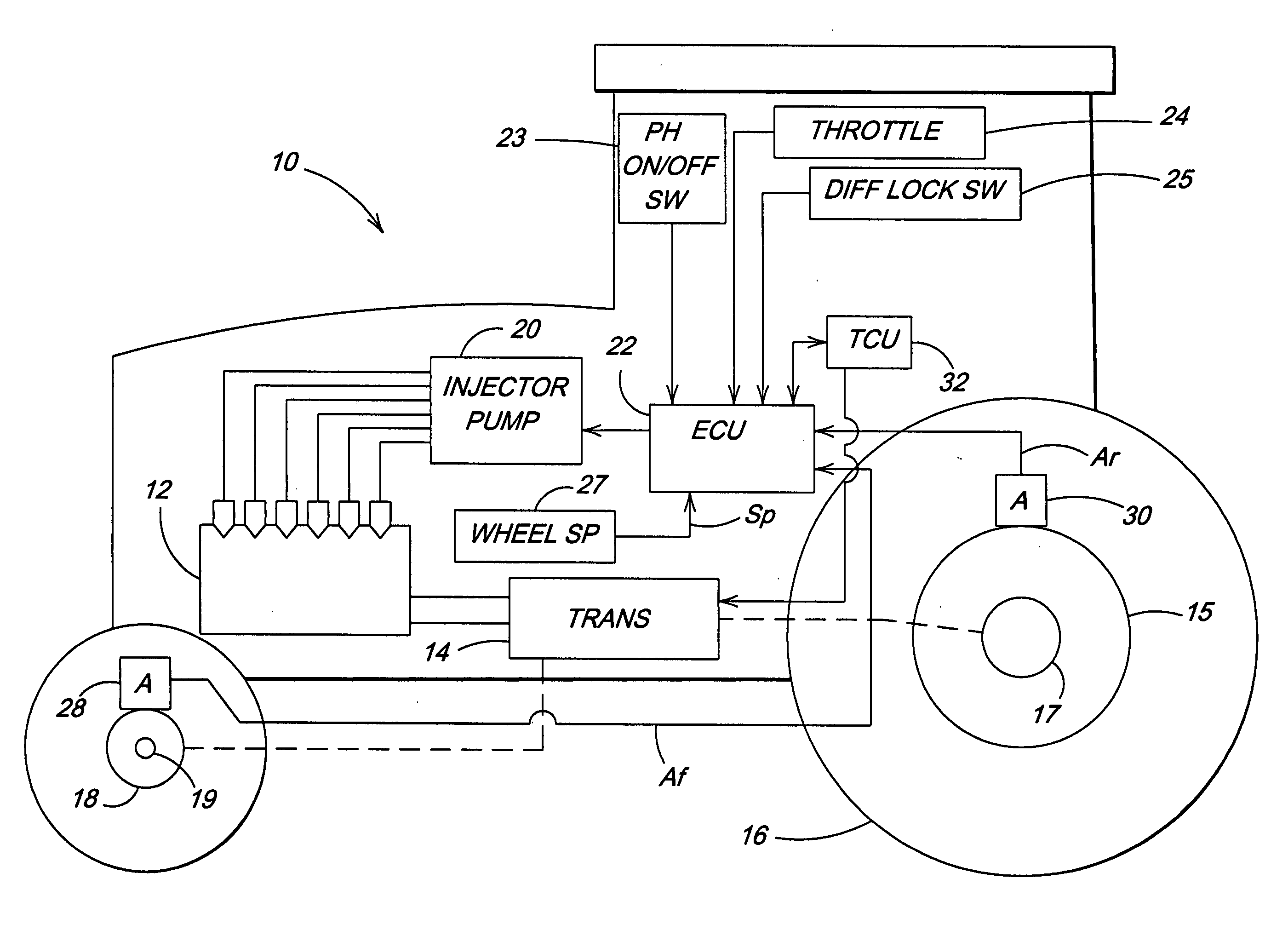
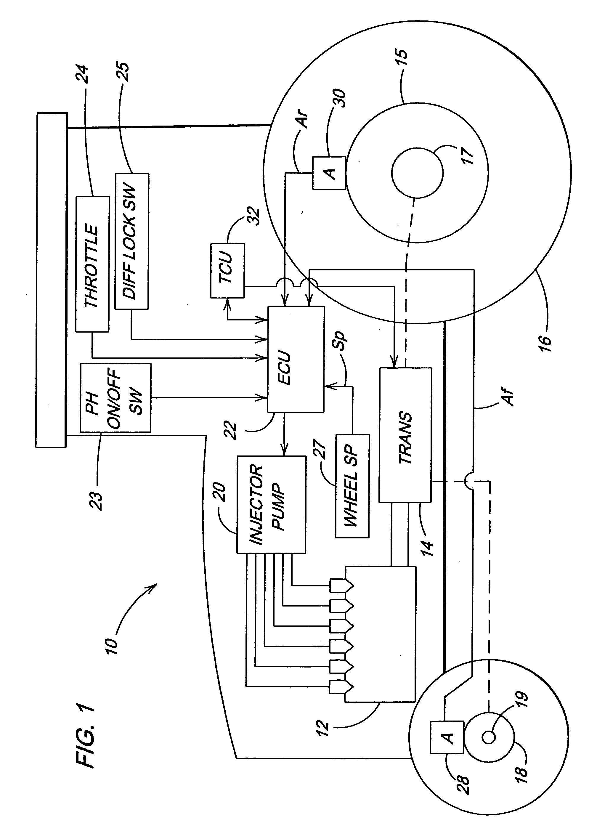
[0019] In FIG. 1, a vehicle 10, such as a agricultural tractor, includes an engine 12 which supplies power to a transmission 14 which has multiple gear ratios, such as a production powershift transmission. The transmission 14 drives rear wheels 15, (including tires 16) mounted on an axle 17, and selectively drives front wheels 18 mounted on a front axle 19. Engine control unit (ECU) 22, which includes an electronic governor (not shown), controls pump 20 which supplies a variable amount of fuel to the engine 12 in response to fuel control signals generated by the ECU 22.

[0020] The ECU 22, in addition to other signals it normally receives, such as a throttle signal from a conventional throttle control or speed command 24. The ECU 22 also receives a status signal from diff lock switch 26 which controls a differential lock (not shown) in the transmission 14.

[0021] A front accelerometer 28 is preferably mounted on or near the front axle 19 and provides to ECU 22 a front acceleration si...


PUM


Abstract

A control system performs a method for controlling pitching and bouncing of a vehicle having an engine driving wheels through a transmission, and having a fuel control unit for supplying a variable amount of fuel to the engine in response to fuel control signals generated by an engine control unit. The method includes, from front and rear acceleration signals, generating vehicle pitch and bounce signals, converting the pitch and bounce signals to RMS pitch and bounce values, generating a fuel offset value as a function of the RMS pitch and bounce values, and modifying fuel delivered to the engine as a function of the fuel offset value. The fuel offset value is operate don by a bi-linear gain function wherein negative values are multiplied by a larger gain and positive values are multiplied by a smaller gain.

Description

FIELD OF THE INVENTION [0001] This invention relates to a system and method for controlling power hop in a vehicle such as an agricultural tractor. BACKGROUND OF THE INVENTION [0002] Power hop for agricultural tractors is a well known phenomena, as described by B. P. Volfson and M. Estrin in “The Slip-Stick Phenomenon in Vehicle Ride Simulation”, published by ASME “Computers in Engineering” 1983 Vol. 1. Power hop occurs most commonly with drawn implements in dry soils. Power hop can also occur on hard surfaces such as concrete or asphalt. It is believed that the power hop condition occurs when the traction force exceeds the stable limit of the tire-to-ground interface. When the traction load / pull reaches this limit, a stick-slip phenomena occurs at the tire-to-ground interface which excites the vehicle bounce and pitch natural frequencies. The resulting bounce and pitch motion is called power hop. Power hop can be pure pitch, pure bounce, or a mixture of bounce and pitch. In some ca...

Claims


Application Information

Patent Timeline
Patent Type & Authority Applications(United States)
IPC IPC(8): G06F19/00
CPCF02D41/021Y10T477/693F02D41/30
Inventor SCHICK, TROY EUGENEVOLFSON, BORIS P.
Owner DEERE & CO
Why Eureka
Try Eureka