Failure detecting system
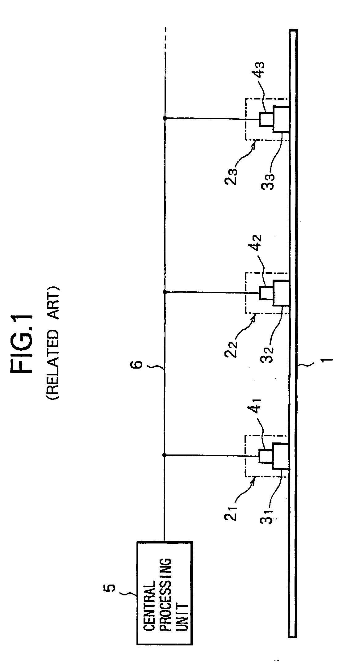
a detection system and failure detection technology, applied in the direction of instruments, specific gravity measurement, transportation and packaging, etc., can solve the problems of complex control of the network comprising terminal devices, communication lines and a central processing unit, and the large size of the attenuation of ultrasonic waves by sleeper and rail fastenings
- Summary
- Abstract
- Description
- Claims
- Application Information
AI Technical Summary
Benefits of technology
Problems solved by technology
Method used
Image
Examples
first embodiment
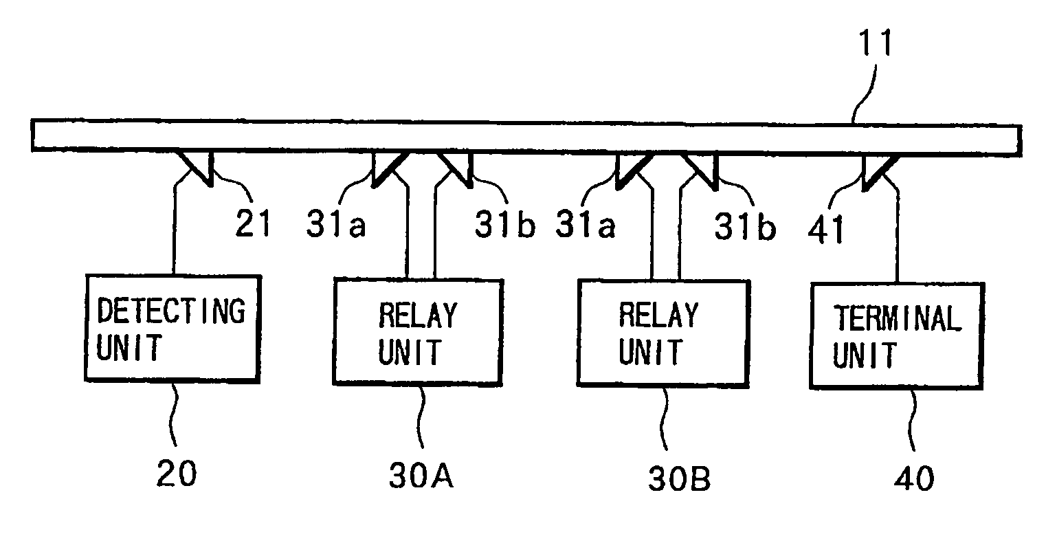
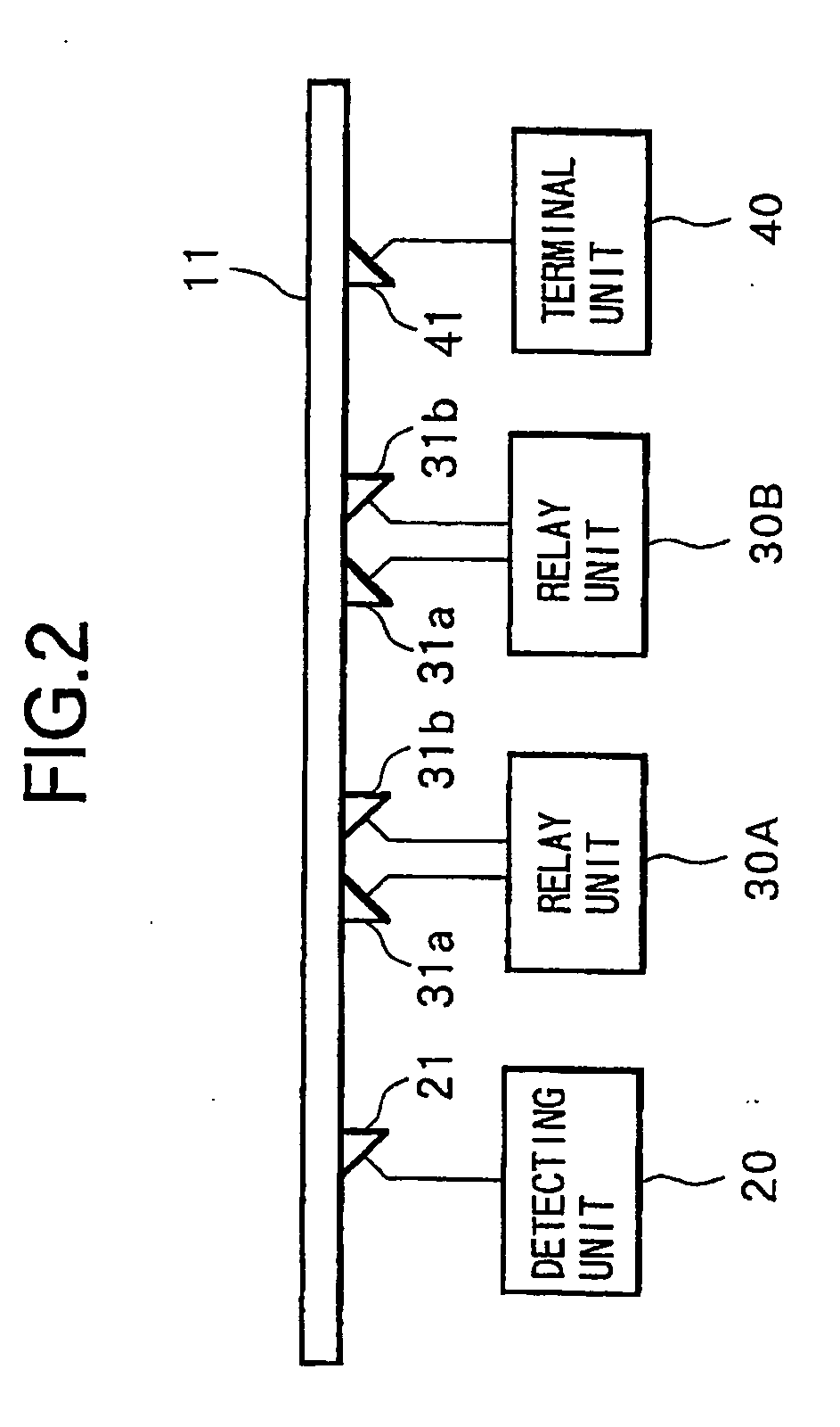
[0053]FIG. 2 shows the present invention, and shows an example applied to a rail break detection.
[0054] In FIG. 2, along a break detection region of a rail 11, being a detection object, a detecting unit 20 is arranged at the start of the detection region and a terminal unit 40 is arranged at the end of the detection region. Furthermore, an appropriate number of relay units 30A and 30B (the present embodiment shows an example with two units arranged) is arranged at intervals in accordance with the length of the detection region. Here, needless to say, the number of relay units is not limited to two.
[0055] The detecting unit 20 is provided with an ultrasonic transducer 21 attached in contact with the rail 11, being a transmission medium, so as to be enable to transmit ultrasonic waves as sound wave to the direction of relay unit 30A, and to receive ultrasonic waves from the direction of relay unit 30A. Furthermore, based on transmission and reception information from transmitting and...
second embodiment
[0072] Next is a description of the present invention that can detect the location of a break accurately regardless of the number of relay units.
[0073] When a signal is received from the direction of detecting unit, each relay unit of the present embodiment relays and transmits the signal to the direction of terminal unit, and also transmits it back to the direction of detecting unit via an ultrasonic transducer 31a. In this case, the construction may be such that each relay unit also outputs information indicative of the signal reception from the receiving circuit 33A to the control circuit 36, as shown by the broken line in FIG. 3. The constructions of the detecting unit and the terminal unit are similar to the first embodiment.
[0074] Next is a description of operations of the second embodiment with reference to operation time charts in FIG. 8 and FIG. 9. The description hereunder assumes that the detecting unit, relay unit and terminal unit are arranged similarly to those in the...
third embodiment
[0088]FIG. 11 shows the present invention in which sound wave is propagated in bi-directions through the transmission medium.
[0089] In FIG. 11, a detecting unit 50, relay units 60A and 60B, and a terminal unit 70, which are arranged along a break detection region of the rail 11, being the transmission medium, have ultrasonic transducers 51, 61 and 71, respectively, as their transmission and reception sections. The ultrasonic transducers 51, 61 and 71 of the units 50, 60 and 70 are mounted, respectively, such that the ultrasonic wave transmission and reception faces thereof are almost at right angles to the propagation direction of the rail 11, being the transmission medium. In this manner, ultrasonic waves as sound wave, transmitted from each of the ultrasonic transducers 51, 61 and 71, are propagated in bi-directions through the rail 11, the right and left directions in the figure.
[0090] The detecting unit 50, which has the same construction as the detecting unit 20, judges whethe...
PUM
 Abstract
Description
Claims
Application Information
 - R&D
- Intellectual Property
- Life Sciences
- Materials
- Tech Scout
- Unparalleled Data Quality
- Higher Quality Content
- 60% Fewer Hallucinations
Browse by: Latest US Patents, China's latest patents, Technical Efficacy Thesaurus, Application Domain, Technology Topic, Popular Technical Reports.
© 2025 PatSnap. All rights reserved.Legal|Privacy policy|Modern Slavery Act Transparency Statement|Sitemap|About US| Contact US: help@patsnap.com


