Vibration-flow-type heating-body cooling device

a cooling device and flow-type technology, applied in the field of vibration-flow-type cooling devices, can solve the problems of inferior cooling performance of circulation-flow-type cooling devices, and achieve the effect of compact pump and low discharge flow ra

Inactive Publication Date: 2006-01-19
DENSO CORP
View PDF1 Cites 12 Cited by
  • Summary
  • Abstract
  • Description
  • Claims
  • Application Information

AI Technical Summary

Benefits of technology

[0024] According to this, by adequately setting a communication relationship between the pump and the plurality of channels using the separator, it is possible to realize the meandering channel system in which fluids vibrate in opposite phase in neighboring channels or the parallel channel system in which a plurality of channel groups are provided, in which fluids vibrate in the same phase in neighboring channels. In this case, it is possible to make the pump compact because a lower discharge flow rate is required for the pump compared to that of the parallel channel system in which fluids vibrate in the same phase in all of the channels.

Problems solved by technology

However, there has been a problem that a vibration-flow-type cooling device is inferior to a circulation-flow-type cooling device in cooling performance.

Method used


Image

  • Vibration-flow-type heating-body cooling device
  • Vibration-flow-type heating-body cooling device
  • Vibration-flow-type heating-body cooling device

Examples


first embodiment

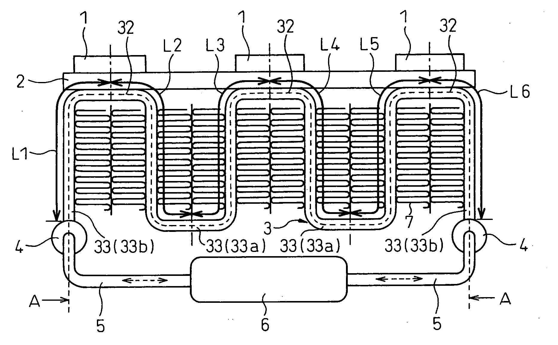
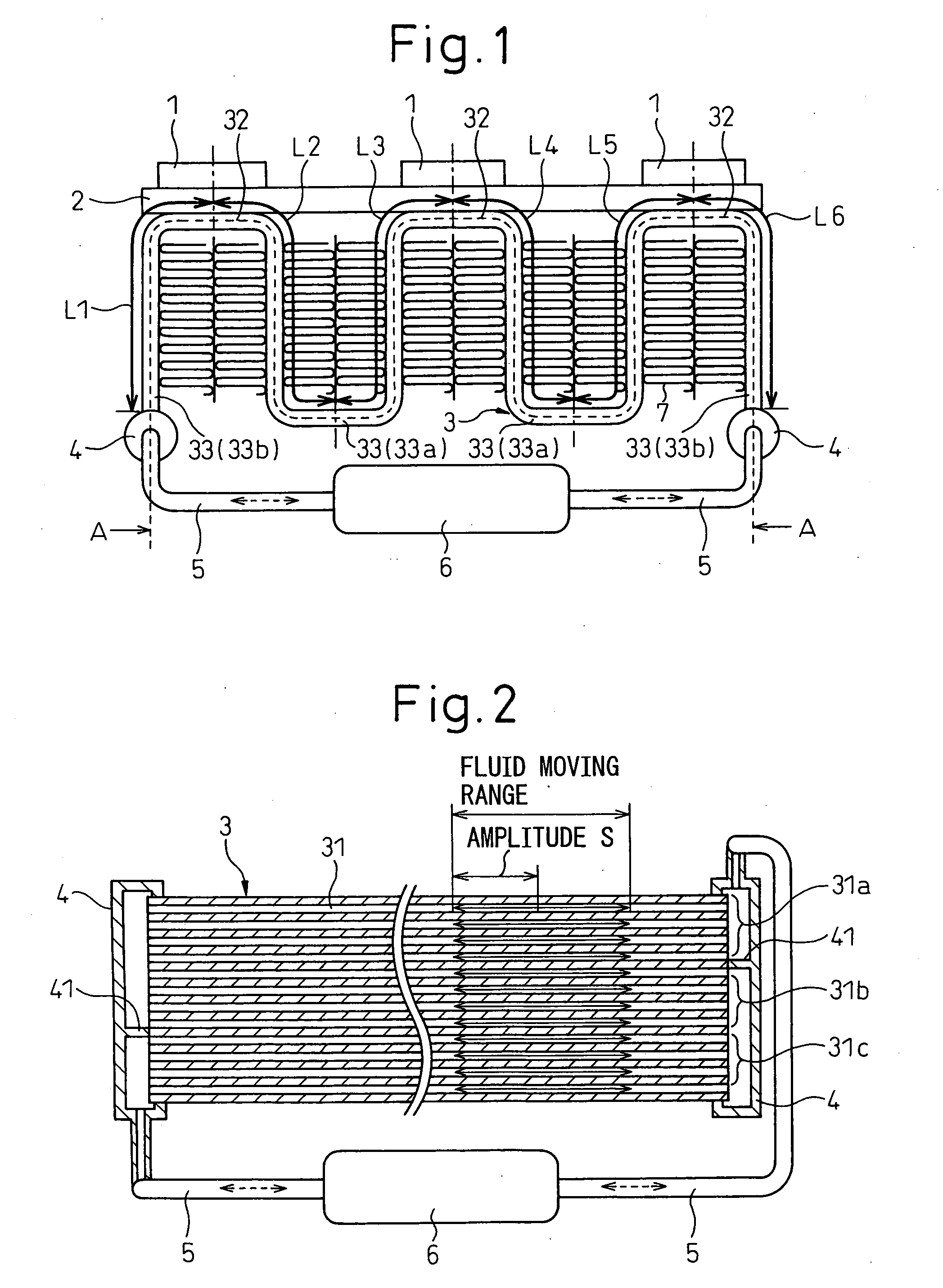
[0043] A first embodiment of the present invention is explained below. FIG. 1 is a schematic configuration diagram of a heating body cooling device according to the first embodiment and FIG. 2 shows an exploded view of a tube 3 in FIG. 1, that is, a section view along the line A-A in FIG. 1.

[0044] The heating-body cooling device according to the present embodiment can be applied to cooling electronic and electrical apparatuses in a mobile phone base station, electronics and electric apparatuses of various industrial equipment (for example, a power element such as IGBT used in an inverter for controlling an industrial motor), etc.

[0045] As shown in FIG. 1 and FIG. 2, a heating body 1 such as a heating element is mounted on a base plate 2 made of a metal material having a high heat conductivity and the base plate 2 is closely fixed to the tube 3 and due to this, the heat of the heating body 1 is transferred to the tube 3 via the base plate 2. The heating bodies 1 are arranged at thr...

second embodiment

[0061] The second embodiment of the present invention is explained below. FIG. 4 is a schematic section view of a heating body cooling device according to the second embodiment and the tube 3 is shown in its exploded view. The same symbols are attached to the parts the same as or similar to those in the first embodiment and the explanation thereof is omitted here.

[0062] As shown in FIG. 4, in the present embodiment, the separator 41 within the header 4 in the first embodiment is not used and the parallel channel system is employed in which the fluids vibrate in the same phase in all of the channels 31.

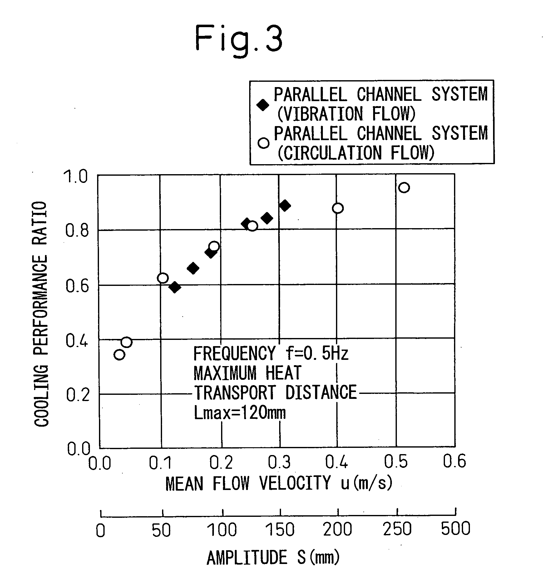
[0063] In the cooling device in the present embodiment also, by setting S>=Lmax, it is possible to improve the cooling performance to the same level as that of the circulation-flow-type cooling device. Further, the structure of the header 4 can be simplified.

third embodiment

[0064] The third embodiment of the present invention is explained below. FIG. 5 is a schematic section view of a heating-body cooling device according to the third embodiment and the tube 3 is shown in its exploded view. The same symbols are attached to the parts the same as or similar to those in the first embodiment and the explanation thereof is omitted here.

[0065] As shown in FIG. 5, in the present embodiment, the number of the separators 41 within the header 4 in the first embodiment is increased and the meandering channel system is employed in which the fluids vibrate in opposite phase in neighboring channels 31.

[0066] In the cooling device in the present embodiment also, by setting S>=Lmax, it is possible to improve the cooling performance to the same level as that of the circulation-flow-type cooling device.


PUM


Abstract

The central position of each heating body 1 in the fluid flow direction is referred to as a heating body central position, the central position of a heat radiating section 33a located between the neighboring heating bodies 1 in the fluid flow direction is referred to as a heat radiating section central position, the end of a heat radiating section 33b connected to a pump 6 on the opposite side of a heat absorbing section is referred to as a heat radiating section front, the distances along the fluid flow from the heating body central position to the heat radiating section central position are referred to as heat transport distances and the distances from the heating body central position to the heat radiating section front are referred to as heat transport distances. S>=the maximum heat transport distance Lmax holds. Lmax is the longest of the heat transport distances.

Description

BACKGROUND OF THE INVENTION [0001] 1. Field of the Invention [0002] The present invention is preferably applicable to a cooling device for cooling an electric apparatus such as an integrated circuit for a computer, a transmitting / receiving modem for processing signals transmitted and received between a mobile phone and its nearest central exchange office, a transmission amplifier for amplifying electromagnetic waves to be transmitted to a mobile phone, an IGBT (power transistor), and an inverter for controlling an industrial motor. [0003] 2. Description of the Related Art [0004] Conventionally, as a cooling device for cooling a heating body such as an electric apparatus, a circulation-flow-type cooling device, which circulates a fluid through a channel to cool a heating body, is widely known. [0005] Further, a vibration-flow-type cooling device has been proposed, which comprises a tube provided with a plurality of channels in parallel through which a fluid flows and a pump for causi...

Claims


Application Information

Patent Timeline
Patent Type & Authority Applications(United States)
IPC IPC(8): F28F3/00
CPCF28D2021/0031F28F13/10H01L23/473H05K7/20272H01L2924/0002H05K7/20927H01L2924/00F28D15/00F28D15/0266
Inventor INOUE, SEIJINARA, KENICHIKOHARA, KIMIOKADOTA, SHIGERUSUZUKI, NOBUNAOHATANO, YUKINORINAKAMURA, FUMIAKIOKADA, NOBUYOSHI
Owner DENSO CORP
Why Eureka
Try Eureka