Bio-electrochemically assisted microbial reactor that generates hydrogen gas and methods of generating hydrogen gas

a microbial reactor and bio-electrochemical technology, applied in the field of bio-electrochemically assisted microbial reactor systems and processes for producing hydrogen gas, can solve the problem of low yield

Active Publication Date: 2006-01-19
PENN STATE RES FOUND +1
View PDF6 Cites 144 Cited by
  • Summary
  • Abstract
  • Description
  • Claims
  • Application Information

AI Technical Summary

Benefits of technology

[0018] In a further embodiment, the wall of the reaction chamber includes two or more portions such as a structural portion and an electrode portion. A structural portion provides structural support for forming and maintaining the shape of the reaction chamber, as in a conventional wall. An electrode portion of a wall may provide structural support for the reaction chamber and in addition has a functional role in a process carried out in an inventive system.

Problems solved by technology

Hydrogen can be produced from certain forms of biomas

Method used


Image

  • Bio-electrochemically assisted microbial reactor that generates hydrogen gas and methods of generating hydrogen gas
  • Bio-electrochemically assisted microbial reactor that generates hydrogen gas and methods of generating hydrogen gas
  • Bio-electrochemically assisted microbial reactor that generates hydrogen gas and methods of generating hydrogen gas

Examples


example 1

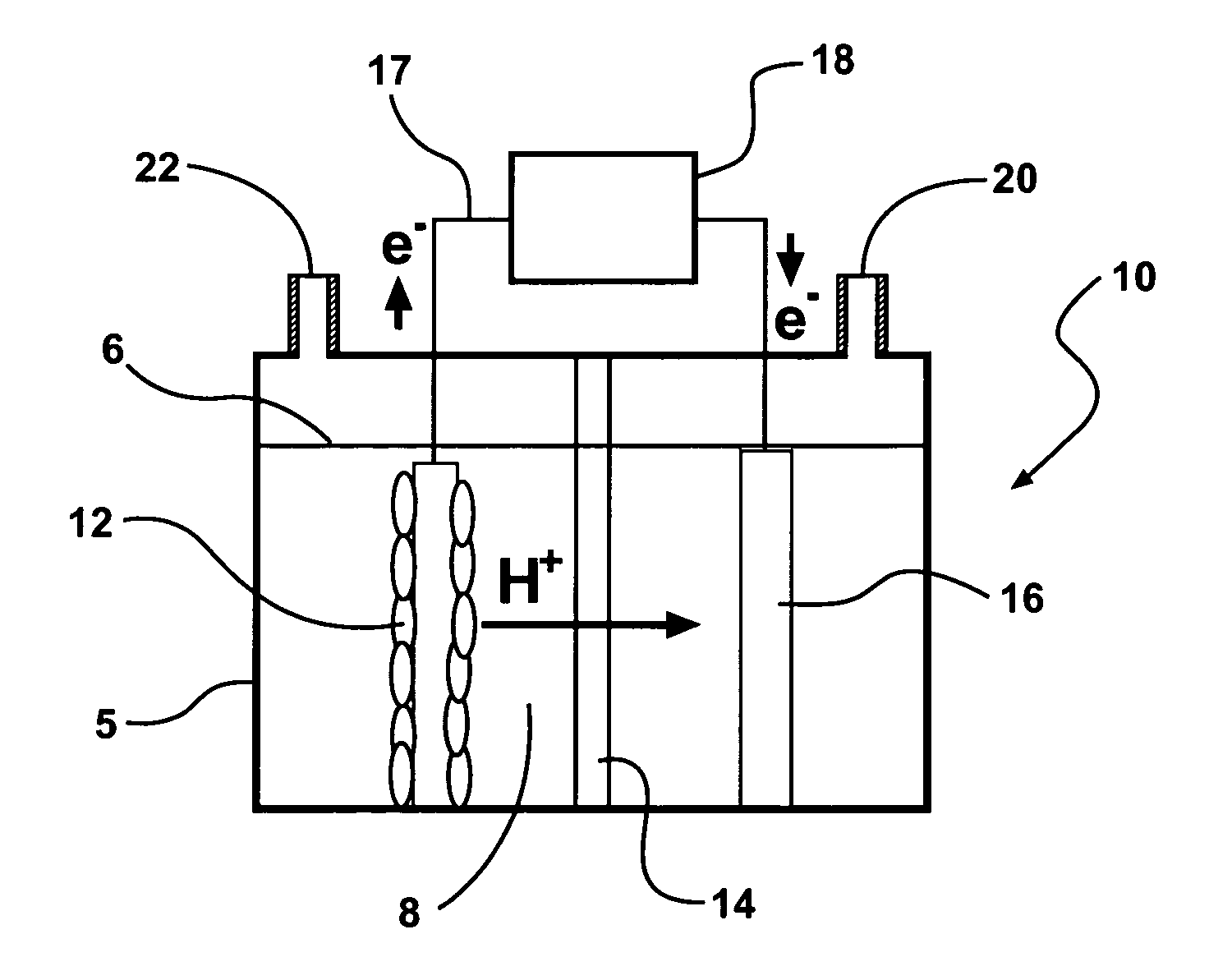
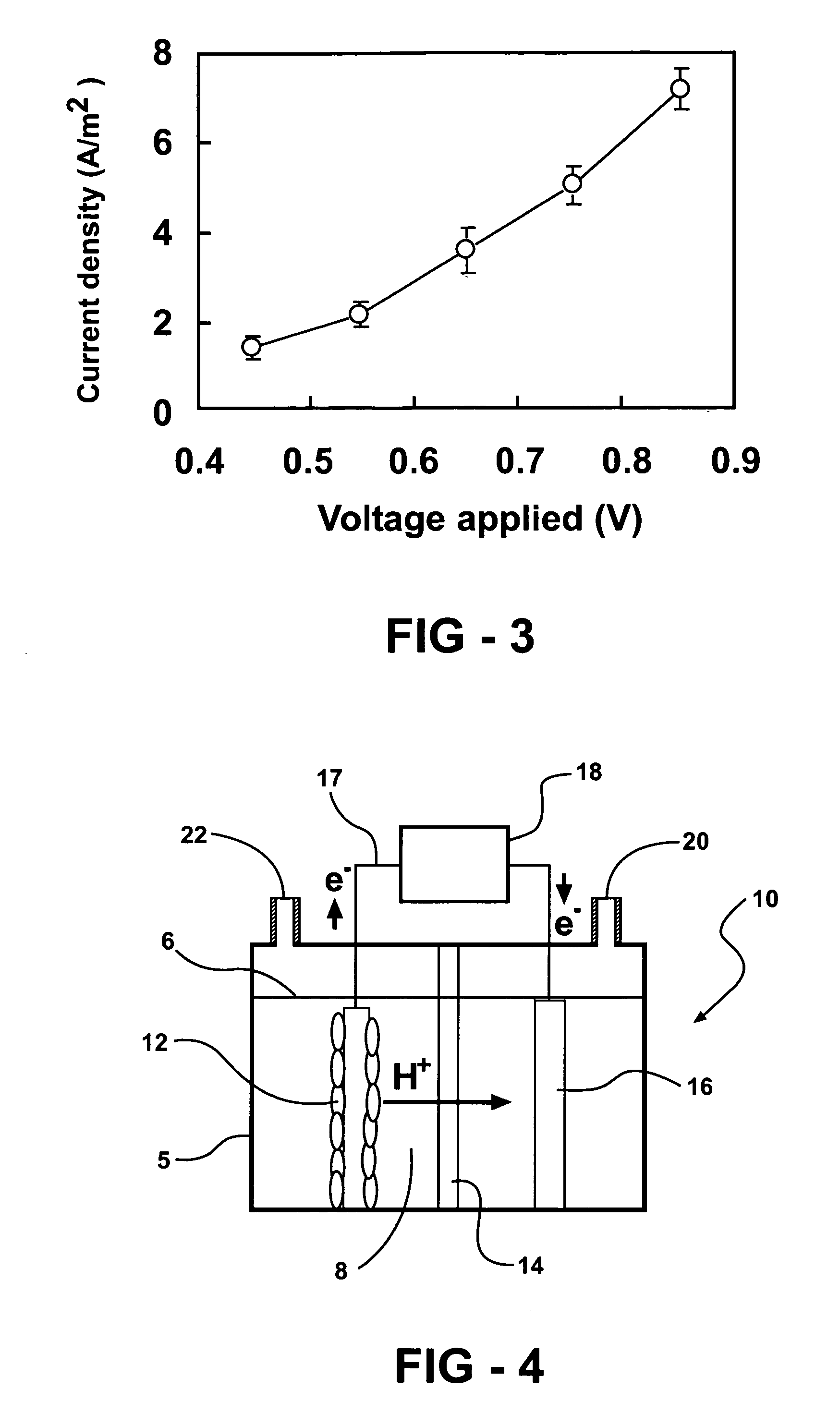
[0112] Exemplary hydrogen-generating reactors are constructed in this example. Exemplary reactors described in this example are two-chamber MFCs with the anode and cathode separated by a proton exchange membrane (PEM; NAFION™ 117) (FIG. 4). The anode electrodes are plain carbon cloth and the cathode electrodes are made of carbon paper containing 0.5 mg-Pt / cm2.

[0113] A first exemplary reactor system is a two-bottle reactor (310 mL-capacity each; Wheaton™ Scientific) with a PEM held by a clamp in a tube separating the chambers, with electrodes spaced 15 cm apart. Instead of sparging the cathode chamber with air, the chamber is sealed and analyzed periodically for hydrogen gas production. Each electrode is 12 cm2 and the proton exchange membrane is 3.5 cm2, and the bottles are filled to 200 mL.

[0114] A second exemplary reactor is based is a tubular shaped reactor. This reactor is converted into a two-chamber system by inserting a PEM into the middle of a 4-cm long cylindrical chamber...

example 2

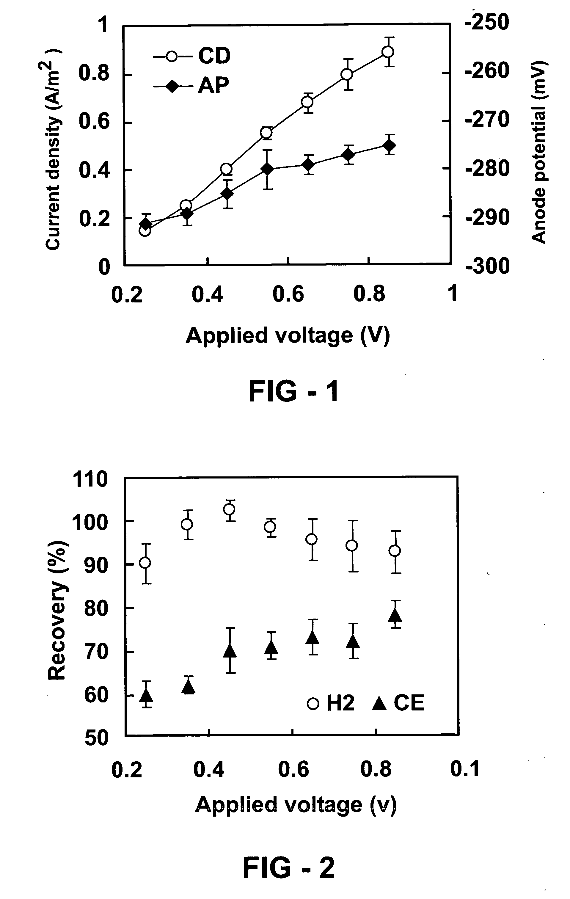
[0119] Measurements of current density are made using a reactor as described in example 1. FIG. 1 shows increased current density (CD) and anode potential (AP) with the applied voltage in an inventive hydrogen generating system described in example 1. Error bars ±S.D. are based on averages measured during stable conditions in three separate batch experiments. Current density increased with the applied voltage from 0.15 A / m2 (250 mV) to 0.88 A / m2 (850 mV) (FIG. 1). The anode potential decreased with the voltage added from −291 mV (250 mV) to −275 mV (850 mV) (FIG. 2). Over 95% of the acetate is typically degraded by the end of a batch cycle (when the reactor is re-filled with fresh medium). This reactor is run for over four months, under various operating conditions, in order to demonstrate that hydrogen generation is stable in this type of reactor.

example 3

[0120] Measurements of hydrogen recovery and Coulombic efficiency as a function of applied voltage are made using a reactor as described in example 1. FIG. 2 shows Hydrogen recovery and Coulombic efficiency (CE) as a function of the applied voltage in a two-chambered hydrogen generating system described in example 1. Error bars ±S.D. are based on averages measured during stable conditions in three separate batch experiments. The recovery of electrons as hydrogen is over 90% (FIG. 2). The Coulombic efficiency, defined as the recovery of total electrons in acetate as current (eq. 1), ranged from 60-78% depending on the applied voltage (FIG. 2). This range in Coulombic efficiency is similar to that obtained in some aerobic MFCs (21, 22). Assuming a maximum possible production of 4 mol-H2 / mol-acetate, a 78% Coulombic efficiency, and 92% current recovery as hydrogen, the overall hydrogen yield is 2.9 mol-H2 / mol-acetate. The recovery of electrons is affected by many factors, including bio...


PUM

PropertyMeasurementUnit
Temperatureaaaaaaaaaa
Lengthaaaaaaaaaa
Angleaaaaaaaaaa

Abstract

Systems and processes for producing hydrogen using bacteria are described. One detailed process for producing hydrogen uses a system for producing hydrogen as described herein, the system including a reactor. Anodophilic bacteria are disposed within the interior of the reactor and an organic material oxidizable by an oxidizing activity of the anodophilic bacteriais introduced and incubated under oxidizing reactions conditions such that electrons are produced and transferred to the anode. A power source is activated to increase a potential between the anode and the cathode, such that electrons and protons combine to produce hydrogen gas. One system for producing hydrogen includes a reaction chamber having a wall defining an interior of the reactor and an exterior of the reaction chamber. An anode is provided which is at least partially contained within the interior of the reaction chamber and a cathode is also provided which is at least partially contained within the interior of the reaction chamber. The cathode is spaced apart at a distance in the range between 0.1-100 centimeters, inclusive, from the anode. A conductive conduit for electrons is provided which is in electrical communication with the anode and the cathode and a power source for enhancing an electrical potential between the anode and cathode is included which is in electrical communication at least with the cathode. A first channel defining a passage from the exterior of the reaction chamber to the interior of the reaction chamber is also included.

Description

REFERENCE TO RELATED APPLICATIONS [0001] This application claims priority of U.S. Provisional Patent Application Ser. Nos. 60 / 588,022, filed Jul. 14, 2004, and 60 / 608,703, filed Sep. 10, 2004, the entire content of each application being incorporated herein by reference.GOVERNMENT SUPPORT [0002] Research carried out in connection with this invention was supported in part by National Science Foundation grant BES-0401885 and United States Department of Agriculture grant 68-3A75-3-150. Accordingly, the United States government may have certain rights in the invention.FIELD OF THE INVENTION [0003] The invention relates to systems and processes for producing hydrogen gas. In particular, the invention relates to bioelectrochemically assisted microbial reactor systems and processes for producing hydrogen gas. BACKGROUND OF THE INVENTION [0004] The global interest in a hydrogen economy has been stimulated by the promise of clean energy production using hydrogen in fuel cells. A reduction in...

Claims


Application Information

Patent Timeline
IPC IPC(8): C25B1/02C25D17/00C25B9/19C25B9/23
CPCC02F3/005C02F2001/46133C02F2001/46161C02F2201/46115Y02E60/528C25B9/00H01M8/16H01M8/186Y02E60/527C25B1/02Y02W10/37Y02E60/50
Inventor LOGAN, BRUCEGROT, STEPHEN
Owner PENN STATE RES FOUND
Why Eureka
Try Eureka