

Electron beam method and apparatus for improved melt point temperatures and optical clarity of halogenated optical materials
a technology of electron beam radiation and optical materials, which is applied in the field of electron beam radiation fabrication of optical materials, can solve the problems of restricted use of waxes, oils and polymers in high temperature applications, reduced melt point of certain waxes, oils and polymers, etc., and achieves enhanced optical properties, improved melt point temperature, and improved optical clarity
- Summary
- Abstract
- Description
- Claims
- Application Information
AI Technical Summary
Benefits of technology
Problems solved by technology
Method used
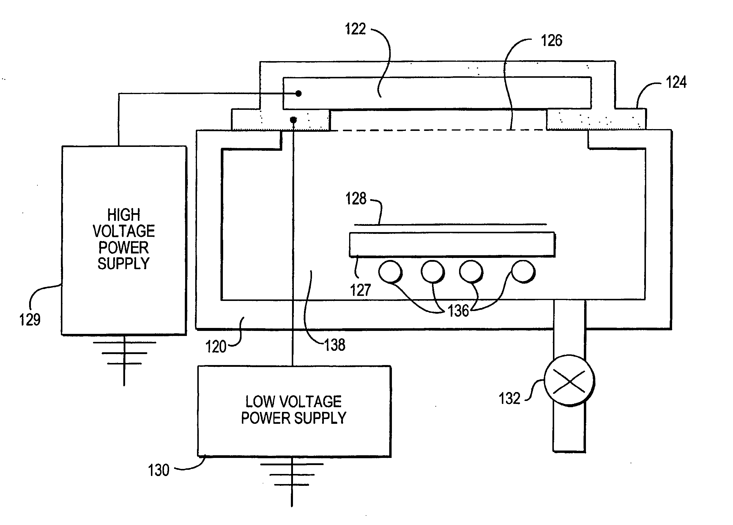
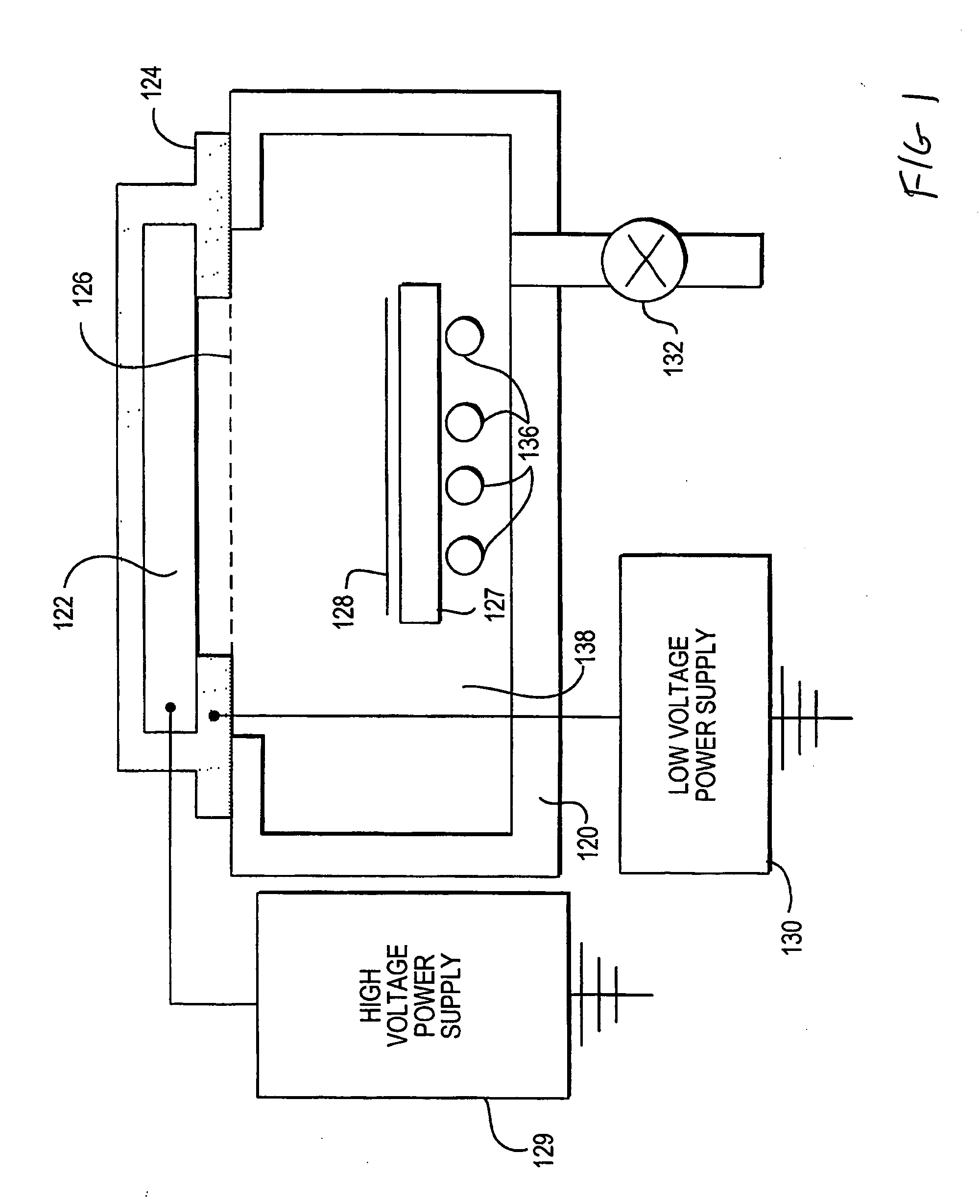
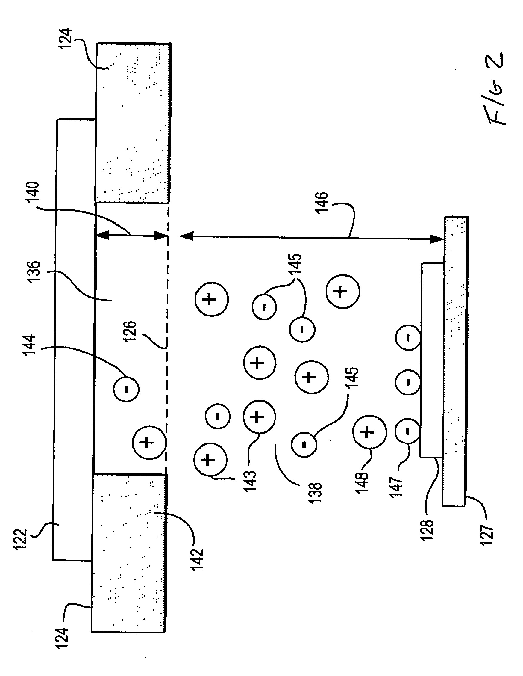
Image

Examples
Embodiment Construction
[0020] The exposure of selected optical materials to electron beam irradiation can convert the existing material into a new state, which exhibits more desirable optical and mechanical properties not present in the un-irradiated material. The introduction of extra bonds within halogenated optical materials, including oils, waxes and polymers, results in higher melt point temperatures and improved optical clarity. Optical clarity means making the halogenated optical material less hazy, more clear, more optically transparent to light with less light scatter.
[0021] The electron beam imparts sufficient energy to the chemical bonds in the optical materials to create scissions, which leads to the formation of additional networking bonds as these reactive entities recombine within the optical material. The change in melt point temperatures and optical clarity, is due to the process of scission and reformation and (to a lesser extent) due to the extraction of low molecular weight components...
PUM
 Abstract
Description
Claims
Application Information