Fiber delivery system with enhanced passive fiber protection and active monitoring

a fiber optic and passive technology, applied in the field of fiber optic systems and methods, can solve the problems of laser-induced fiber failure, fiber failure, fiber failure,

Active Publication Date: 2006-01-19
CONTINUUM ELECTRO OPTICS
View PDF15 Cites 53 Cited by
  • Summary
  • Abstract
  • Description
  • Claims
  • Application Information

AI Technical Summary

Problems solved by technology

Laser induced fiber failures tend to result from two sources: stray light, and cladding mode light.
However, if a fiber holder or the outer layers are very close to the injection end, stray light can burn them immediately or generate thermo-stress which may gradually lead to a fiber failure.
It is evident that strong cladding light can also result in fiber failures.
Unfortunately, the bare fiber does not attenuate the cladding mode light, and the thin sapphire holder can hardly strip off the cladding mode light either.
Therefore, the fiber connector is still vulnerable to cladding mode light.
This method has disadvantages of slow response and low accuracy.
This method, however, has its limitations, especially for pulsed lasers.
It is somewhat inconvenient, however, to embed sensors and electronics in the middle of a fiber link.

Method used


Image

  • Fiber delivery system with enhanced passive fiber protection and active monitoring
  • Fiber delivery system with enhanced passive fiber protection and active monitoring
  • Fiber delivery system with enhanced passive fiber protection and active monitoring

Examples


Embodiment Construction

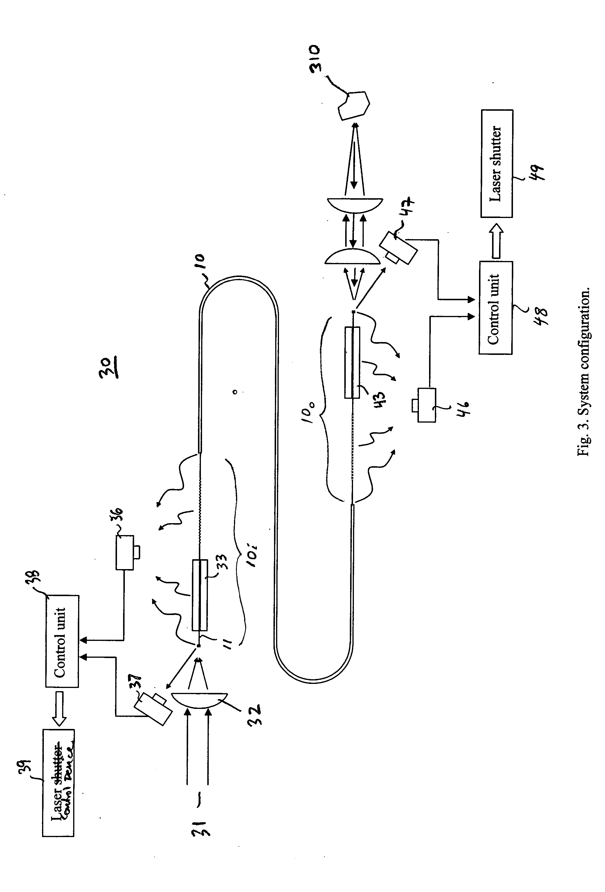
[0027]FIG. 3 shows a schematic representation of an exemplary embodiment of an optical fiber laser delivery system 30 in accordance with the present invention. In an exemplary materials processing embodiment, the system 30 delivers a laser beam 31 applied to an input port of the system via an optical fiber 10 to a work piece 310.

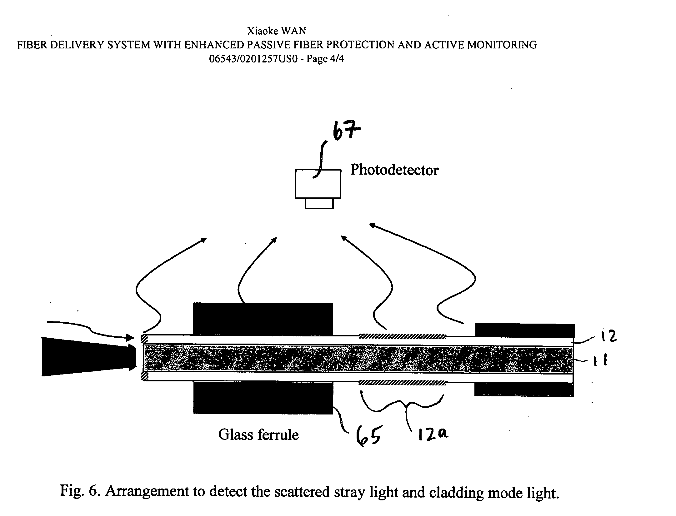
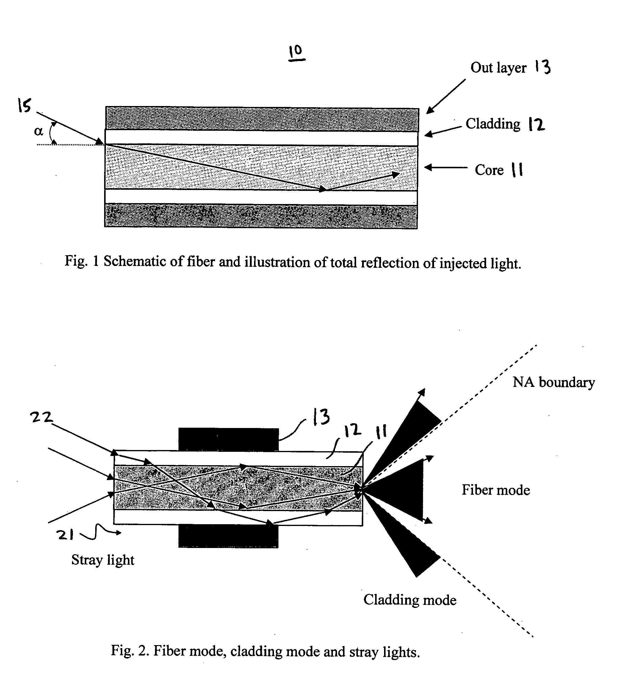
[0028] In the exemplary system of FIG. 3, the laser beam 31 is focused into the fiber core 11 of a fiber 10 with a plano-convex lens 32. A portion 10i of the fiber 10 proximate to the input is bare; i.e., it does not include any outer layers of material. The bare fiber portion 10i is held by a glass ferrule 33 which is transparent to any stray light and also strips off a portion of cladding mode light. Over at least a portion of its length, the bare fiber portion 10i has a rough surface so that it further scatters off stray light and cladding mode light. The rough surface can be created in a variety of ways including, for example, sanding with a fine sand p...


PUM

PropertyMeasurementUnit
flexibilityaaaaaaaaaa
resistanceaaaaaaaaaa
total reflectionaaaaaaaaaa

Abstract

In an optical fiber system for delivering laser, a laser beam is focused onto an optical fiber at an injection port of the system. The end portions of the fiber have cladding treatments to attenuate stray light and cladding mode light, so as to enhance the protection of the outer layer joint points. Photodetector sensors monitor scattered stray light, cladding mode light, and / or transmitted cladding mode light. Sensor signals are provided to a control unit for analyzing the fiber coupling performance. If need be, the control unit can control a laser shutter or the like to minimize or prevent damage. In materials processing applications, the photodetector signals can be analyzed to determine the processing status of a work piece.

Description

FIELD OF THE INVENTION [0001] The present invention relates to fiber optic systems and methods and more particularly to fiber optic systems and methods for delivering laser. BACKGROUND INFORMATION [0002] Fiber delivered laser is widely used in materials processing such as drilling and cutting. Compared to traditional optical beam delivery methods, fiber delivery has several advantages including high flexibility, remote laser transportability, and enhanced safety. [0003] Fiber delivery systems often include sensor units for monitoring the overall beam delivery integrity and the process condition of the work piece. Such sensor units are particularly important for avoiding fiber failures in high power laser applications. It is also desirable to have passive protection features to enhance the system's resistance to fiber failures. [0004] As shown in FIG. 1, an optical fiber 10 generally consists of a fiber core 11, fiber cladding 12, and one or more outer layers 13. A light beam 15 can ...

Claims


Application Information

Patent Timeline
Patent Type & Authority Applications(United States)
IPC IPC(8): G02B6/00
CPCB23K26/03B23K26/032G02B6/2852G01M11/35G02B6/02B23K26/428B23K26/707
Inventor WAN, XIAOKE
Owner CONTINUUM ELECTRO OPTICS
Why Eureka
Try Eureka