Pulse modulation circuit

Active Publication Date: 2006-01-19
MITSUBISHI ELECTRIC CORP
View PDF13 Cites 3 Cited by
  • Summary
  • Abstract
  • Description
  • Claims
  • Application Information

AI Technical Summary

Benefits of technology

[0013] With this structure, since the on/off ratio is adjusted by the switch, and an on/off ratio of the harmonic mixer per se can be added to the adjusted on/off ra

Problems solved by technology

However, at the actual supply voltage at the off time of the pulse, there arises such a problem that the on/off ratio of the output power in the switching operation is reduced due to noises of several ten

Method used


Image

  • Pulse modulation circuit
  • Pulse modulation circuit
  • Pulse modulation circuit

Examples


first embodiment

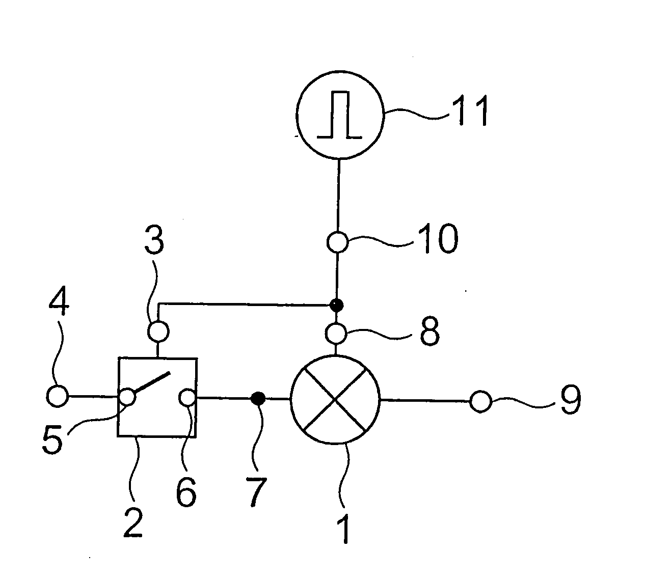
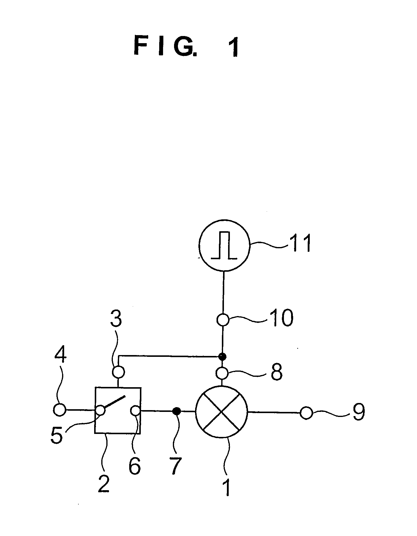
[0022]FIG. 1 shows the structure of a pulse modulation circuit in accordance with a first embodiment of the present invention. The pulse modulation circuit according to the present invention is a pulse modulation circuit using a harmonic mixer 1 that inputs an LO signal (local oscillation wave) and a DC pulse, mixes the second harmonic wave of the LO signal with the DC pulse, and outputs an RF pulse signal. The harmonic mixer 1 inputs the LO signal to a harmonic mixer LO signal input terminal 7, inputs a DC pulse signal to a harmonic mixer IF signal input terminal 8, mixes those inputted signals together, and outputs a sum frequency component of the second harmonic wave of the LO signal and the DC pulse signal to an RF signal output terminal 9. It is assumed that the frequency of the LO signal is fLO, the frequency of the DC pulse signal is fIF, and the frequency of the RF signal is fRF, a relation of fRF=2fLO+fIF is established.

[0023] As shown in FIG. 1, the pulse modulation circu...

second embodiment

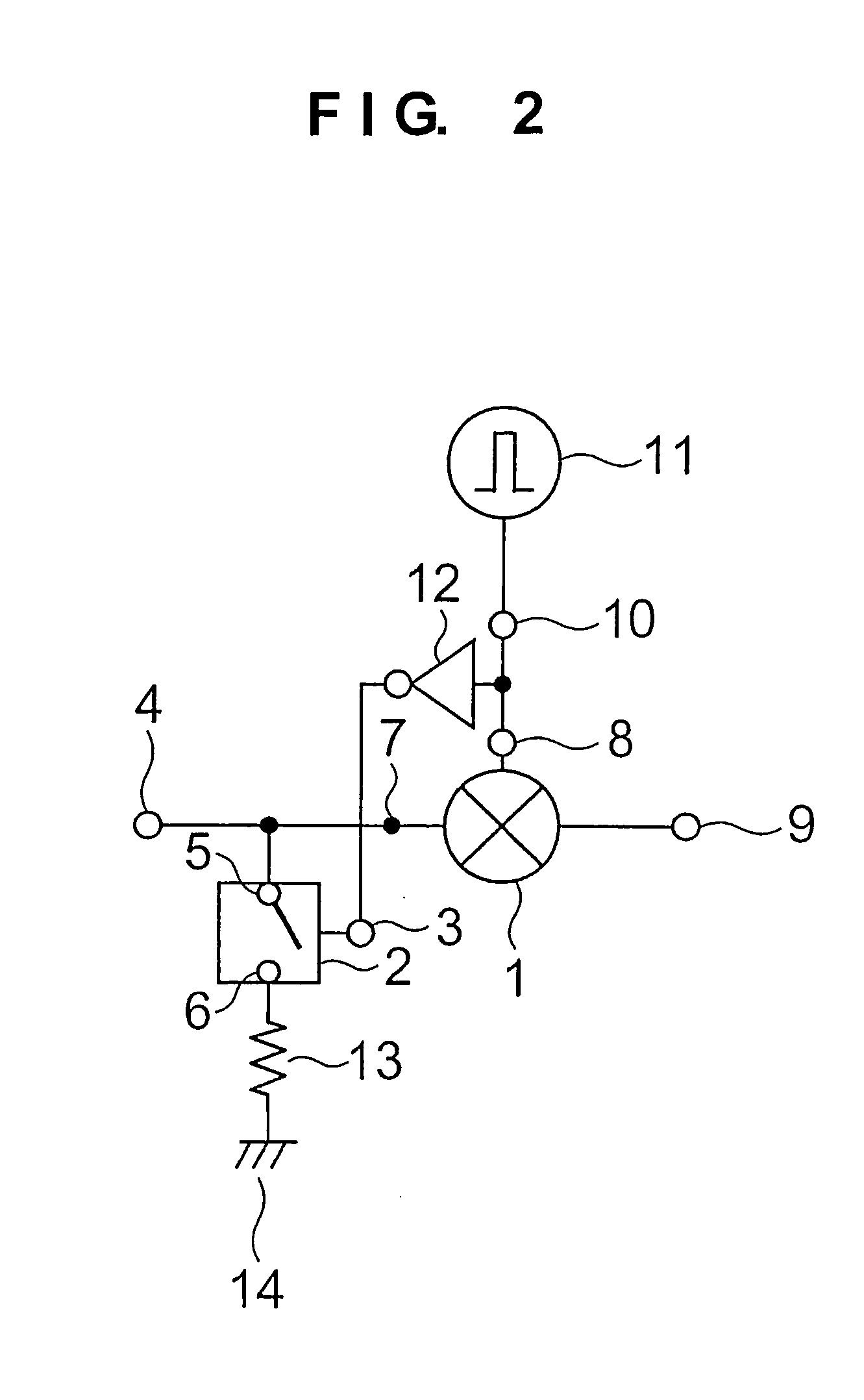
[0027]FIG. 2 shows the structure of a pulse modulation circuit in accordance with a second embodiment of the present invention. As shown in FIG. 2, the pulse modulation circuit according to this embodiment includes a harmonic mixer 1, a single pole single throw (SPST) switch 2, and a pulse signal generator 11, as in the structure shown in FIG. 1. In this embodiment, the SPST switch 2 is connected in parallel with the fore stage of the harmonic mixer 1. That is, an LO signal input terminal 4 for applying the LO signal is connected to an SPST switch input terminal 5 that is disposed in the SPST switch 2, and an SPST switch output terminal 6 that is disposed in the SPST switch 2 is grounded to a grounding point 14 through a terminating resistor 13. Also, a harmonic mixer LO signal input terminal 7 is disposed between the SPST switch 2 and the harmonic mixer 1. A pulse signal supply terminal 10 that is connected to a pulse signal generator 11 is connected to the SPST switch 2 through an...

third embodiment

[0031]FIG. 3 shows the structure of a pulse modulation circuit in accordance with a third embodiment of the present invention. As shown in FIG. 3, the pulse modulation circuit according to this embodiment includes a harmonic mixer 1, a single pole double throw (SPDT) switch A15, an SPDT switch B16, a band rejection filter 17 (hereinafter referred to as BRF 17″), and a pulse signal generator 11. In this embodiment, the SPDT switch A15, the SPDT switch B16, and the BRF17 constitute a switching circuit (switch) . The switching circuit is connected in series to the fore stage of the harmonic mixer 1, and the LO signal is inputted to the harmonic mixer 1 through the switching circuit. That is, an LO signal input terminal 4 for supplying the LO signal is connected to an input terminal 30 that is disposed in the SPDT switch A15, and an output terminal 31 that is disposed in the SPDT switch B16 is connected to the harmonic mixer 1 through the harmonic mixer LO signal input terminal 7. In ad...


PUM


Abstract

Provided is a pulse modulation circuit that improves the on/off operation and improves the on/off ratio of an output power of the entire pulse modulation circuit in the switching operation. The pulse modulation circuit inputs a local oscillation wave and a DC pulse signal, mixes a second harmonic wave of the local oscillation wave with the DC pulse signal, and outputs an RF pulse signal. The pulse modulation circuit includes: a switch that inputs the local oscillation wave and attenuates the local oscillation wave at an off time more than at an on time; and a harmonic mixer that inputs the local oscillation wave affected by the switch and the DC pulse signal, mixes the second harmonic wave of the local oscillation wave with the DC pulse signal, and outputs the RF pulse signal, in which the switch is allowed to conduct the switching operation together with the harmonic mixer according to the DC pulse signal.

Description

BACKGROUND OF THE INVENTION [0001] 1. Field of the Invention [0002] The present invention relates to a pulse modulation circuit, and more particularly to a pulse modulation circuit used for communication or radar. [0003] 2. Description of the Related Art [0004] Up to now, modulation circuits, which include a harmonic mixer, are used in a Pulse-Doppler radar apparatus for a vehicle or the like (for example, refer to JP 2000-338233 A). [0005] In the pulse modulation circuit disclosed in JP 2000-338233 A, the harmonic mixer is equipped with a harmonic mixer local oscillation (LO) signal input terminal for inputting an LO wave, and a harmonic mixer IF signal input terminal for inputting the IF signal that is generated by the pulse signal generator as well as an RF signal output terminal for outputting the RF signal into which the inputted LO wave and IF signal are mixed. [0006] The operation will be described. The harmonic mixer inputs the LO wave to the harmonic mixer LO signal input t...

Claims


Application Information

Patent Timeline
IPC IPC(8): H04B1/26
CPCH03D7/12
Inventor ONO, MASAYOSHIKAWAKAMI, KENJI
Owner MITSUBISHI ELECTRIC CORP
Why Eureka
Try Eureka