Probe actuation

a technology of scanning probe and actuation, which is applied in the direction of scanning probe techniques, nanotechnology, instruments, etc., can solve the problems of difficult control of the bending of the probe accurately and with a large range of motion, and achieve the effect of increasing the power, intensity and modulation bandwidth of the probe illumination, and optimizing the

Active Publication Date: 2015-01-08
INFINITESIMA
View PDF1 Cites 13 Cited by
  • Summary
  • Abstract
  • Description
  • Claims
  • Application Information

AI Technical Summary

Benefits of technology

[0024]The third and fourth aspects of the invention provide an improved system and method in which two modulated radiation beams are used to drive the motion of the probe instead of one, enabling the probe to be driven with higher power than in Yamashita et al, thus enabling the intensity and modulation bandwidth of the probe illumination to be increased.
[0025]The beams may be centred on the same location on the probe. However more preferably the optical system is arranged to direct the centres of the beams onto different locations on the probe. This enables the location of each beam to be chosen to optimise its effect.

Problems solved by technology

A problem with such an arrangement is that it can be difficult to control the bending of the probe accurately and with a large range of motion.

Method used


Image

  • Probe actuation
  • Probe actuation
  • Probe actuation

Examples


Embodiment Construction

)

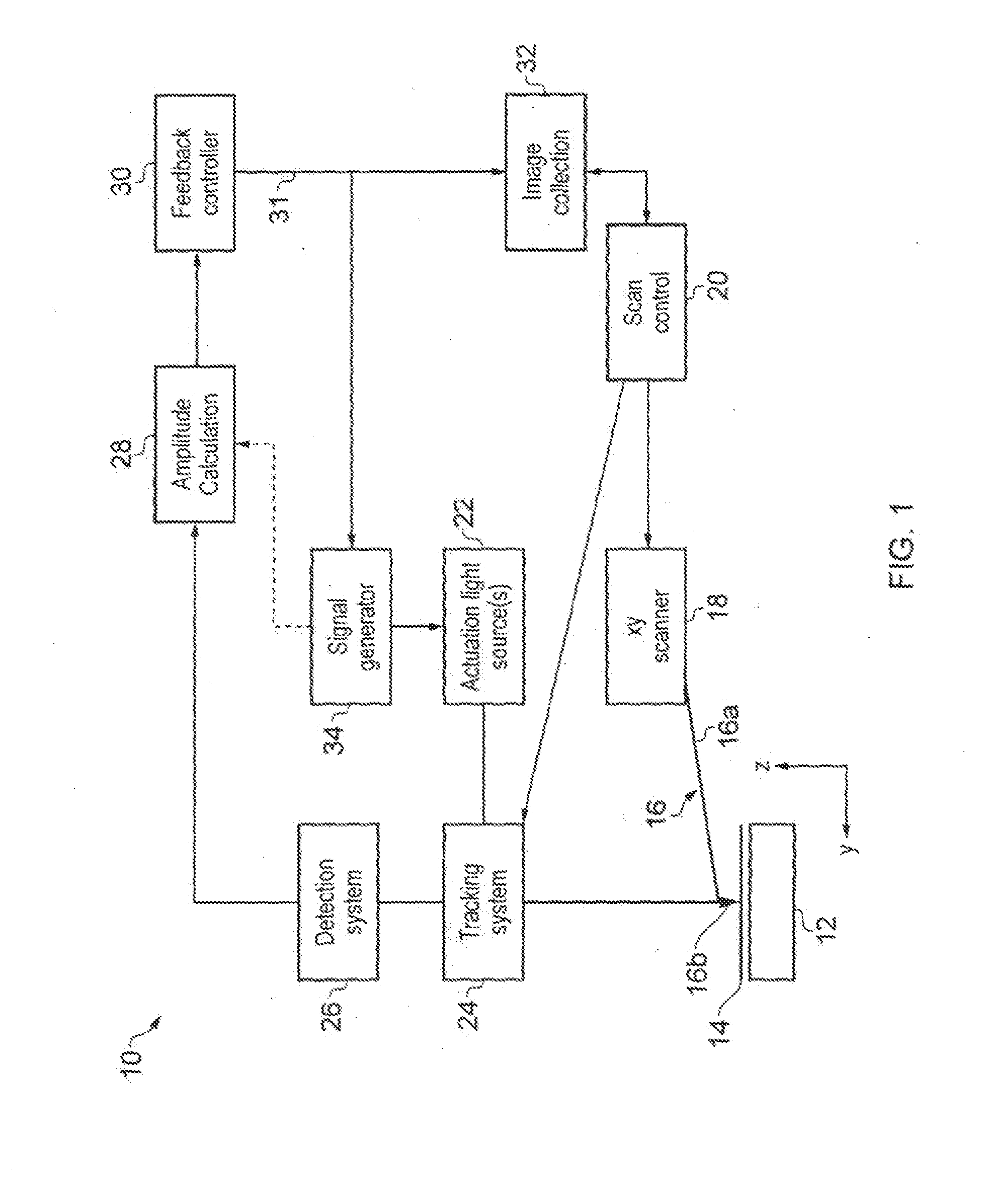
[0049]With reference to FIG. 1, a novel microscope 10 that incorporates an embodiment of a z actuation system in accordance with the present invention is shown. The microscope 10 comprises a stage 12 on which a sample 14 to be investigated by a probe 16 is mounted. The probe 16 comprises a cantilever beam 16a and a tip 16b, which tapers to a fine point, and which is located towards a distal end of the cantilever beam. The other (proximal) end of the cantilever beam is fixed to a mount. The mount and probe 16 are connected to piezoelectric xy drivers 18 that are operable by a scan controller 20 to move the probe 16 across the sample surface in the plane (x,y) of the sample 14.

[0050]The cantilever 16a is of a type referred to as a thermal bimorph. That is, it is composed of two (or more) materials, with differing thermal expansions. Typically, this will be a silicon or silicon nitride base with a gold or aluminium coating. The coating extends the length of the cantilever 16a and cove...


PUM


Abstract

A method of driving a probe of a scanning probe microscope. The intensities of first and second radiation beams are modulated; and the beams are directed simultaneously onto the probe whereby each beam heats the probe and causes the probe to deform, typically by the photothermal effect. The optical system is arranged to direct the centres of the beams onto different locations on the probe. This enables the location of each beam to be chosen to optimise its effect. A lens receives the first and second beams and focuses them onto the probe. A beam combiner is arranged to receive and combine the beams and direct the combined beams towards the probe.

Description

RELATED APPLICATIONS[0001]The present application is a National Phase of International Application Number PCT / GB2013 / 050194 filed Jan. 29, 2013, and claims priority from Japanese Application Number 1201640.8, filed Jan. 31, 2012.FIELD OF THE INVENTION[0002]The present invention relates to a method of driving a probe of a scanning probe microscope, and apparatus for use in such a method.BACKGROUND OF THE INVENTION[0003]H. Yamashita, T. Uchihashi, N. Kodera, A. Miyagi, D. Yamamoto, and T. Ando, “Tip-sample distance control using photo-thermal actuation of a small cantilever for high-speed atomic force microscopy”, Rev. Sci. Instrum. 78:083702 (5 pages) (2007) describes an atomic force microscope (AFM) in which photothermal bending of a cantilever is induced by an intensity-modulated infrared laser. A red laser is also used to detect deflection of the cantilever. Both lasers are focused onto the cantilever by an objective lens.[0004]A problem with such an arrangement is that it can be ...

Claims


Application Information

Patent Timeline
Patent Type & Authority Applications(United States)
IPC IPC(8): G01Q10/00
CPCG01Q20/02B82Y35/00G01Q10/045G01Q10/00
Inventor HUMPHRIS, ANDREWZHAO, BIN
Owner INFINITESIMA
Why Eureka
Try Eureka