

Gas stove with thermoelectric generator
- Summary
- Abstract
- Description
- Claims
- Application Information
AI Technical Summary
Benefits of technology
Problems solved by technology
Method used
Image

Examples
Embodiment Construction
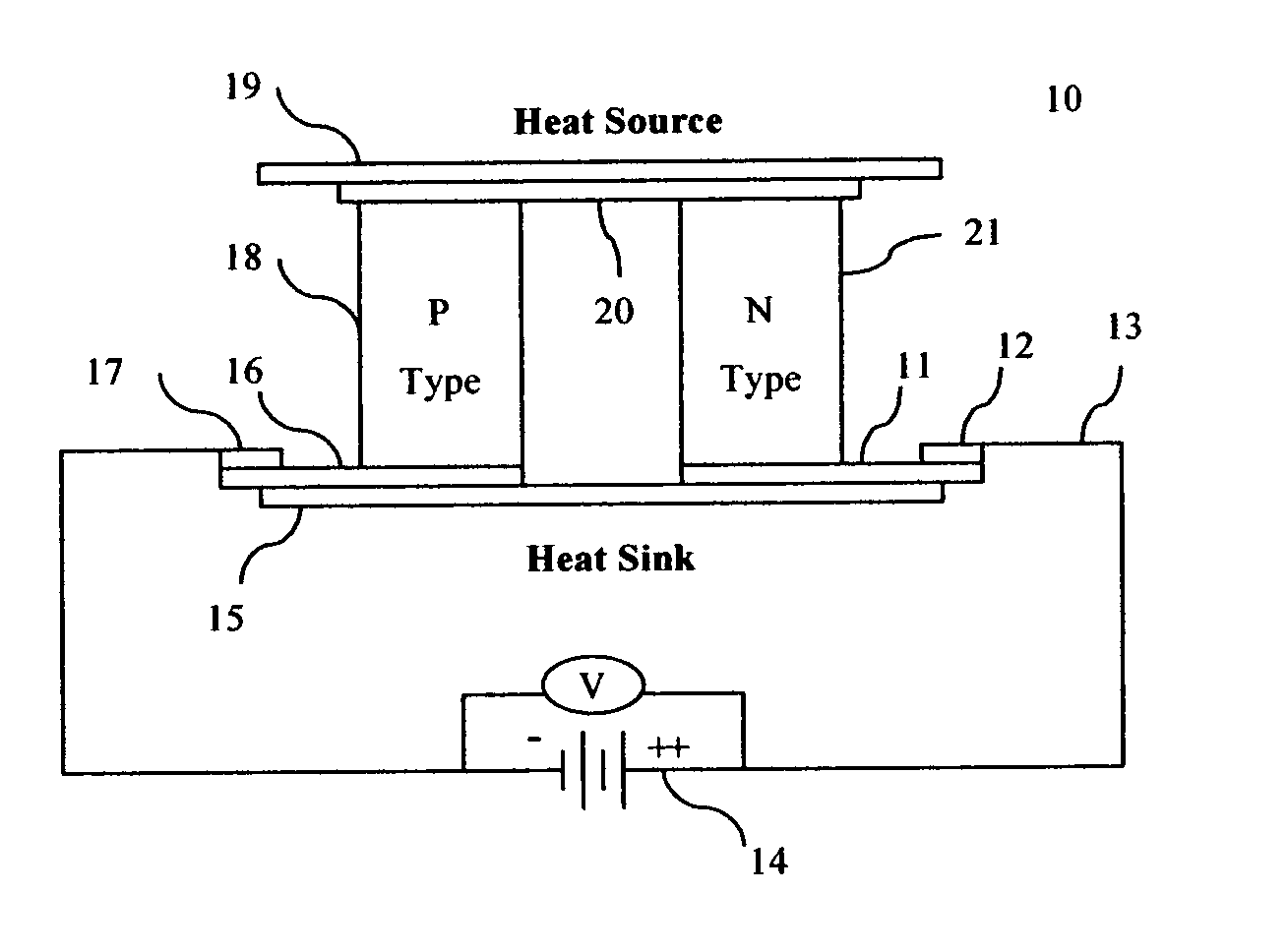
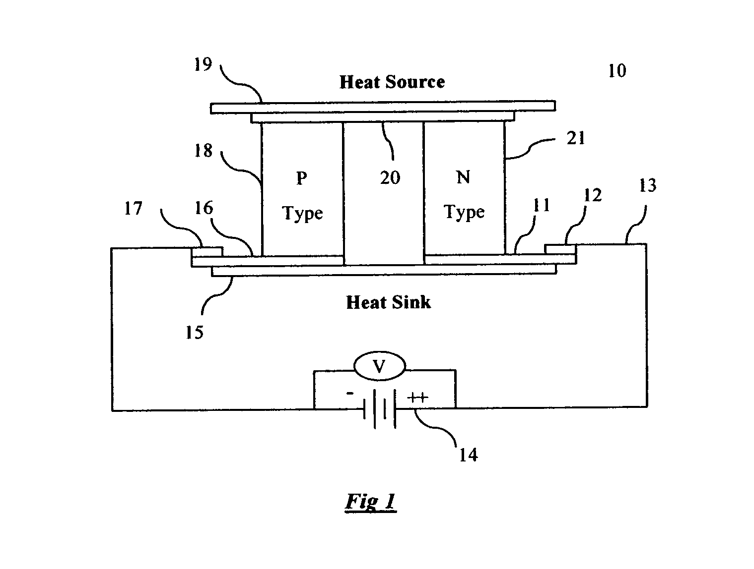
[0013]FIG. 1 is a schematic representation of operating principle associated with thermoelectric module 10 in accordance with the present invention. Electrical circuit 13 is a typical circuit associated with thermoelectric elements or thermocouples to convert heat energy into electrical energy. Electrical circuit 13 generally includes two dissimilar or similar materials differing in the type of majority current carrier such as n-type thermoelectric element 21 and p-type thermoelectric element 18. Thermoelectric elements 21 and 18 are typically arranged in an alternating n-type element to p-type element serpentine configuration. In almost all thermoelectric devices, semiconductor materials with these characteristics are connected electrically in series and thermally in parallel. N-type semiconductor materials have more electrons than necessary to complete a perfect molecular lattice structure. P-type semiconductor materials have fewer electrons than necessary to complete a lattice st...
PUM
 Abstract
Description
Claims
Application Information