Solid state microoptoelectromechanical system (moens) for reading photonics diffractive memory

a micro-optoelectromechanical and photonics technology, applied in the field can solve the problems of slow addressing system of these previous devices, mechanical components of these previous devices need frequent maintenance to correct errors and dysfunction, and achieve the effect of small size of photonics diffractive memory reading systems

Inactive Publication Date: 2006-01-26
RES INVESTMENT NETWORK
View PDF14 Cites 11 Cited by
  • Summary
  • Abstract
  • Description
  • Claims
  • Application Information

AI Technical Summary

Benefits of technology

[0007] In view of the foregoing, it is an object of the present invention to provide an improvement in higher speed and smaller size of photonics diffractive memory reading systems.
[0010] It is a still a further object of the present invention to design a solid state reading system that can be rapidly manufactured in large quantities and low cost out of existing resources. SUMMARY OF THE INVENTION

Problems solved by technology

Previous holographic devices for recording information in a highly multiplexed volume holographic memory, and for reading the information out, require components and dimensions having a large size which places a limit on the ability to miniaturize these systems.
Because previous holographic devices use motors and large-scale components such as mirrors and lenses, the addressing systems of these previous devices are slow.
Furthermore, the mechanical components of these previous devices need frequent maintenance to correct errors and dysfunction coming, for instance, from wear and friction (i.e., tribology effect).
Furthermore, previous addressing systems are expensive because they use complex systems for control.
Thus, their prices cannot be lowered by mass production.
Moreover, previous devices are not economical in their energy consumption.
Even when previous addressing devices are accurate when new, the wear and friction of the interacting surfaces that are in relative motion lowers their accuracy with time.

Method used


Image

  • Solid state microoptoelectromechanical system (moens) for reading photonics diffractive memory
  • Solid state microoptoelectromechanical system (moens) for reading photonics diffractive memory
  • Solid state microoptoelectromechanical system (moens) for reading photonics diffractive memory

Examples


Embodiment Construction

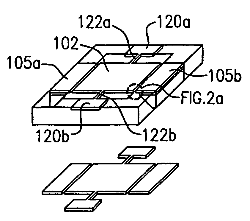
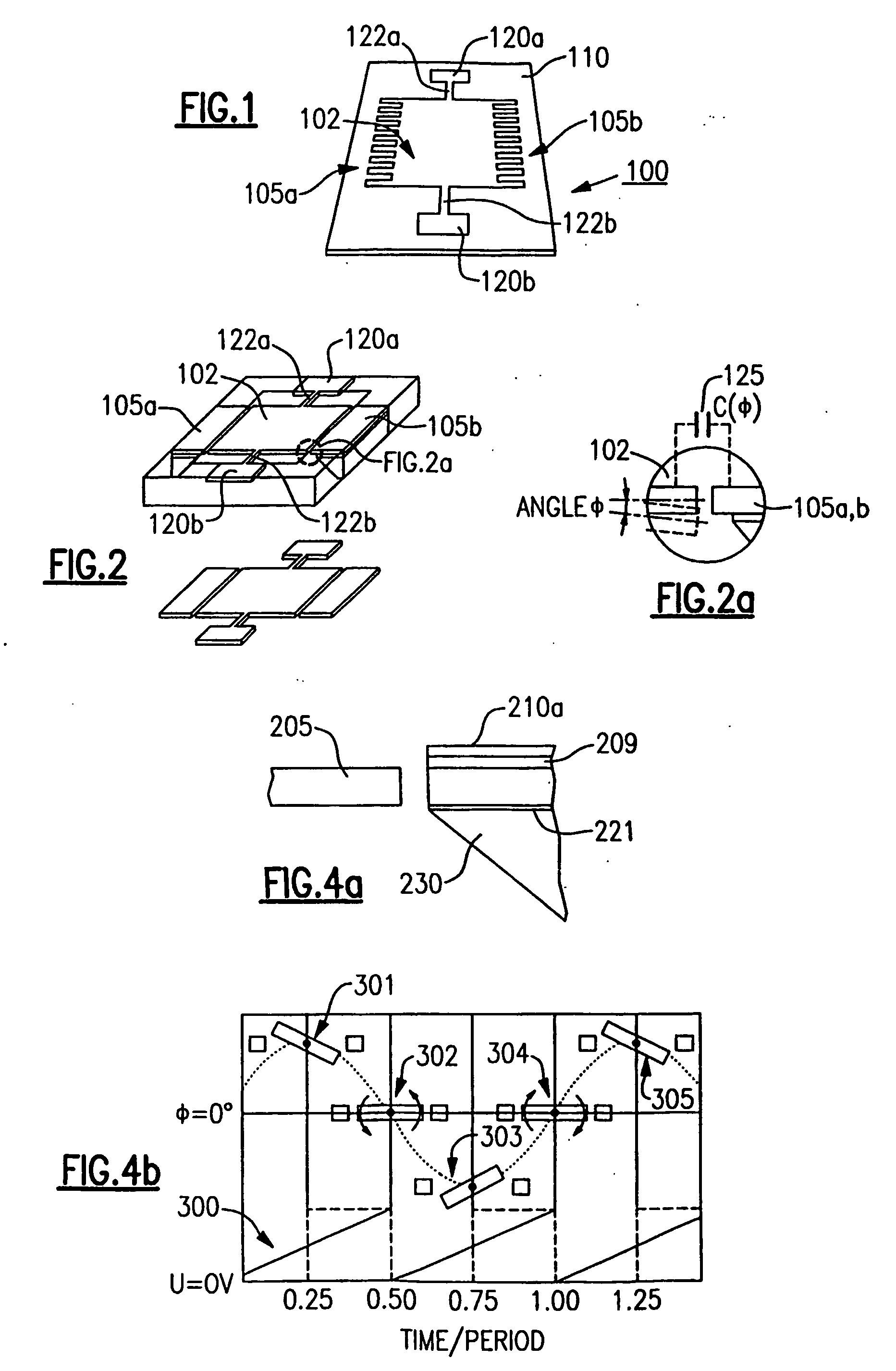
[0036] The compact architecture for diffractive optics systems in accordance with the present invention integrates a number of components into a compact package, including an acousto-optic deflector and a microoptoelectromechanical system (MOEMS) device which reduces the addressing component of a reading system for a photonics diffractive memory to a matchbox size. The reading system is made of solid-state components. The mirrors are built in CMOS technology resulting in the advantage that the reading system can be mass-produced at low cost.

[0037] Various diffractive recording / reading processes have been developed in the art and further details can be found in the book Holographic Data Storage, Springer (2000) edited by H. J. Coufal, D. Psaltis, and G. T. Sincerbox. In this specification, the term “diffractive” is used throughout to differentiate prior art holographic technology used for 3-D image generation from diffractive technology necessary for the generation of a storage medi...


PUM

PropertyMeasurementUnit
thicknessaaaaaaaaaa
angle of deflectionaaaaaaaaaa
thickaaaaaaaaaa

Abstract

The present invention comprises a solid-state system for reading information from a photonics diffractive memory. An acousto-optic deflector directs a convergent light beam onto a micr-mirror array which then reflects the light beam onto the photonics diffractive memory at a predetermined point and angle so as to access a packet of information. The compact architecture for this diffractive optics systems in accordance with the present invention integrates a number of components into a compact package, including an acousto-optic deflector and a microoptoelectromechanical system (MOEMS) mirror array whose elements oscillate with a sznchronized frequency adapted to that of the acousto-optic deflector. This architecture reduces the addressing component of a reading system for a photonics diffractive memory to a matchbox size.

Description

FIELD OF THE INVENTION [0001] The present invention generally relates to a photonics diffractive memory. In particular, the present invention relates to an apparatus for reading information from the photonics diffractive memory. BACKGROUND OF THE INVENTION [0002] The large storage capacities and relative low costs of CD-ROMS and DVDs have created an even greater demand for still larger and cheaper optical storage media. Holographic memories have been proposed to supersede the optical disc as a high-capacity digital storage medium. The high density and speed of the holographic memory comes from three-dimensional recording and from the simultaneous readout of an entire packet of data at one time. The principal advantages of holographic memory are a higher information density (1011 bits or more per square centimeter), a short random access time (˜100 microseconds and less), and a high information transmission rate (109 bit / sec). [0003] In holographic recording, a light beam from a cohe...

Claims


Application Information

Patent Timeline
Patent Type & Authority Applications(United States)
IPC IPC(8): G11C8/02G11B7/0065G11B7/085G11B7/135G11C13/04
CPCG11B7/0065G11B7/08564G11C13/047G11C13/04G11C13/042G11B7/1362
Inventor KIEFFER, RENAUDTAKAKURA, YOSHITATEFONTAINE, JOELEL HAFIDI, IDRISSGRZYMALA, ROMUALDAMEYRUEIS, PATRICK
Owner RES INVESTMENT NETWORK
Why Eureka
Try Eureka